Hydraulic pressure braking clamp device

A hydraulic brake and caliper technology, applied in the field of hydraulic brake calipers, can solve problems such as troublesome replacement of brake pads

Active Publication Date: 2013-05-22
华伍轨道交通装备(上海)有限责任公司
View PDF6 Cites 24 Cited by
  • Summary
  • Abstract
  • Description
  • Claims
  • Application Information

AI Technical Summary

Problems solved by technology

However, it is troublesome to replace the brake pads of the hydraulic brake caliper device used in the braking system of

Method used


Image

  • Hydraulic pressure braking clamp device
  • Hydraulic pressure braking clamp device
  • Hydraulic pressure braking clamp device

Examples


Embodiment 1)

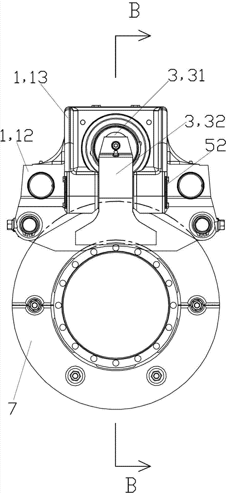
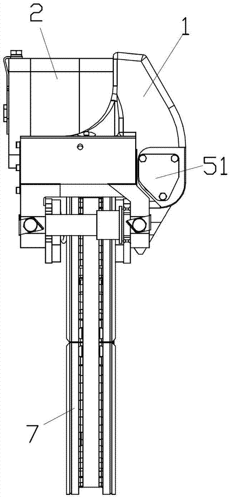
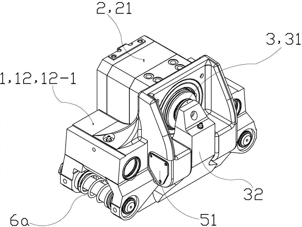
[0132] See Figure 1 to Figure 4 and Figure 7 , The hydraulic brake caliper device of this embodiment is mainly composed of a caliper base 1 , a brake cylinder 2 , a lever member 3 , a lever pin 4 , a left cover 51 , a right cover 52 and a caliper assembly 6 . The lever member 3 is mainly composed of a pressure plate 31 and a lever 32 .

[0133] See Figure 5 and Image 6 , The clamp base 1 is a cast steel integral part, mainly composed of a brake cylinder installation part 11, a brake pin installation part 12, a lever pin left end installation part 13 and a lever pin right end installation part 14.

[0134] The brake cylinder mounting part 11 is mainly composed of a base plate 11-1 and a mounting plate 11-2. The base plate 11-1 is arranged horizontally. The mounting plate 11-2 is arranged vertically, and its body is provided with front and rear through holes as the central hole 11-3 of the brake cylinder installation part 11, and the body of the mounting plate 11-2 is a...

Embodiment 2)

[0233] See Figure 30 and Figure 31 , The remaining parts of this embodiment are the same as those in Embodiment 1, except that the left brake pin 61a and the right brake pin 61b each have only one pin hole 61-1 located at the rear end. Corresponding to the brake pad pin of this structure, in this embodiment, the threaded pins only have left rear threaded pin 67a2 and right rear threaded pin 67b2, but no left front threaded pin 67a1 and right front threaded pin 67b1; the anti-loosening buckle only has left rear anti-loosening Buckle 66a2 and right rear anti-loosening buckle 66b2, but without left front anti-loosening buckle 66a1 and right front anti-loosening buckle 66b1. This embodiment adopts the brake pin of this structure, which makes the replacement of the brake more convenient.


PUM


Abstract

The invention provides a hydraulic pressure braking clamp device which comprises a clamp base, a brake cylinder, a lever member, a lever pin and a clamp assembly. The brake cylinder mainly comprises a piston member, a push rod assembly, a gate adjustment assembly, a disc spring assembly and a manual adjustment shaft assembly. The clamp assembly mainly comprises a clamp left assembly, a clamp right assembly, a front gate piece and a rear gate piece. The clamp assembly and the brake cylinder are fixedly arranged on the clamp base. The brake cylinder brakes and remits a train brake disc by means of driving of the lever member to the clamp assembly. The hydraulic pressure braking clamp device can automatically adjust braking gaps between the gate pieces of a hydraulic pressure clamp and wheels, is good in adjustment accuracy, high in adjustment efficiency, safe, reliable, and compact in structure, meets railway vehicle installation requirements of lower floor boards, is convenient and fast in replacement of the expendable gate pieces, and saves maintenance time and cost.

Description

technical field [0001] The invention relates to a rail vehicle braking device, in particular to a hydraulic brake caliper in a low-floor light rail vehicle braking device. Background technique [0002] Light rail is the abbreviation of light rail transit, and light rail transit is a kind of urban rail transit. According to international standards, urban rail transit trains can be divided into three types: A, B, and C, corresponding to train widths of 3 meters, 2.8 meters, and 2.6 meters, respectively. The rail transit that uses A-type or B-type trains is called subway, and uses 5 to 8 marshalling trains; the rail transit that uses C-type trains is called light rail transit, and uses 2 to 4 marshalling trains. Axle weight and platform length. Both the subway and the light rail use the international standard double track with a gauge of 1435 mm as the train track, which is the same as the track specification used by the national railway trains, and there is no so-called weig...

Claims


Application Information

Patent Timeline
IPC IPC(8): B61H1/00
Inventor 吴萌岭倪成权王敬祎宗全喜
Owner 华伍轨道交通装备(上海)有限责任公司
Why Eureka
Try Eureka