IR Camera and Method for Presenting IR Information

a technology of information and camera, applied in the field of information camera and information presentation method, can solve the problem that different types of gas do not necessarily work, and achieve the effect of eliminating the effect of camera movemen

Active Publication Date: 2009-12-03
FLIR SYST AB
View PDF7 Cites 51 Cited by
  • Summary
  • Abstract
  • Description
  • Claims
  • Application Information

AI Technical Summary

Benefits of technology

[0017]In a preferred embodiment processing device is arranged to filter out small changes between the images to eliminate the effects of camera movements.
[0018]Preferably, the processing device is arranged to align and stabili

Problems solved by technology

Such cameras are specially designed only for gas detection

Method used


Image

  • IR Camera and Method for Presenting IR Information
  • IR Camera and Method for Presenting IR Information
  • IR Camera and Method for Presenting IR Information

Examples


Embodiment Construction

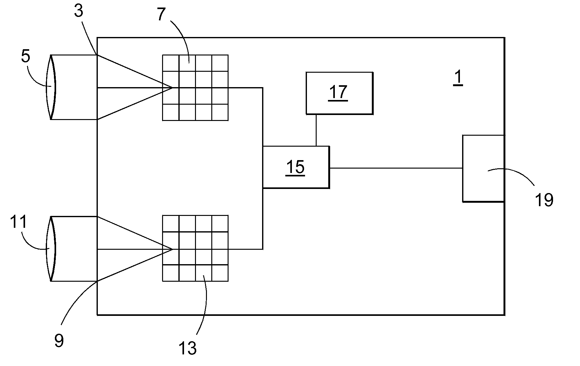
[0025]FIG. 1 shows, schematically, a camera 1 that may be used according to the invention. The camera comprises a first imaging part 3 for capturing thermal images based on IR radiation, The first imaging part comprises optics 5 for focusing IR radiation onto a first focal plane array 7 The camera also comprises a second imaging part 9 for capturing visible light images. The second imaging part 9 comprises optics 11 for focusing visible light onto a second focal plane array 13. The camera 1 also comprises a processing device 15 for receiving and processing IR image data from the first focal plane array 7 and visible light image data from the second focal plane array 13. Each imaging part is devised as is well known in the art. As the skilled person will understand one or more processing units may be arranged between the respective focal plane array 7, 13 and the processing device 15, for processing of image data in ways known in the art. For clarity, however, no such units are shown...


PUM


Abstract

A camera (1) arranged to generate an IR image (21) and a visible light image (23) is proposed, said camera comprising a thermal imaging part (3) for registering IR radiation from a first field of view, a visible light imaging part (9) for registering visible light from a second field of view at least partially overlapping with the first field of view, and a processing device (15) for processing the information related to the registered IR radiation and the registered visible light information. The processing device (15) is arranged to identify any moving objects that are detectable by the thermal imaging part (3) and not by the visible light imaging part (9), and presenting said moving objects, if any, in such a way that they will be easily recognizable by an operator.

Description

TECHNICAL FIELD[0001]The present invention relates to a camera for providing IR images and visible light images as defined in the preamble of claim 1, a method using such a camera, as defined in the preamble of claim 10 and a computer program product as defined in the preamble of claim 18.BACKGROUND AND RELATED ART[0002]In many applications there is a desire to detect the presence of gas. For example, there is often a need to monitor gas pipes for leakages. Many gases are not visible with visible-light cameras, since they do not absorb light in the visible range.[0003]Cameras exist that are specially adapted for gas detection. Such cameras operate in a wave length range where the gas is easily detectable. Such cameras are specially designed only for gas detection, and will not necessarily work for different types of gas. It would be possible to use an IR camera for imaging gas since gas generally fluctuates, but it will not appear very clearly in the thermal image especially in the ...

Claims


Application Information

Patent Timeline
IPC IPC(8): G01J5/00
CPCG01J5/0014G01J5/0846H04N5/332H04N5/144H04N5/33G01J2005/0077H04N23/11
Inventor HARGEL, MARTIN
Owner FLIR SYST AB
Why Eureka
Try Eureka