
Optical filter and plasma display device having the same

a plasma display device and optical filter technology, applied in the field of flat panel displays, can solve the problems of abnormal operation of electronic equipment, adversely affecting human health, and deterioration of purity, so as to improve the viewing angle range, improve the brightness room contrast of the plasma display device, and minimize luminance loss

Inactive Publication Date: 2009-12-03
SAMSUNG SDI CO LTD
View PDF8 Cites 6 Cited by
  • Summary
  • Abstract
  • Description
  • Claims
  • Application Information

AI Technical Summary

Benefits of technology

[0008]In accordance with the present invention an optical filter capable of minimizing the luminance loss under the external light-free condition, and a plasma display device having the same, are provided.
[0009]Further in accordance with the present invention an optical filter capable of minimizing the luminance loss through the active reaction at external environments, and a plasma display device having the same, are provided.
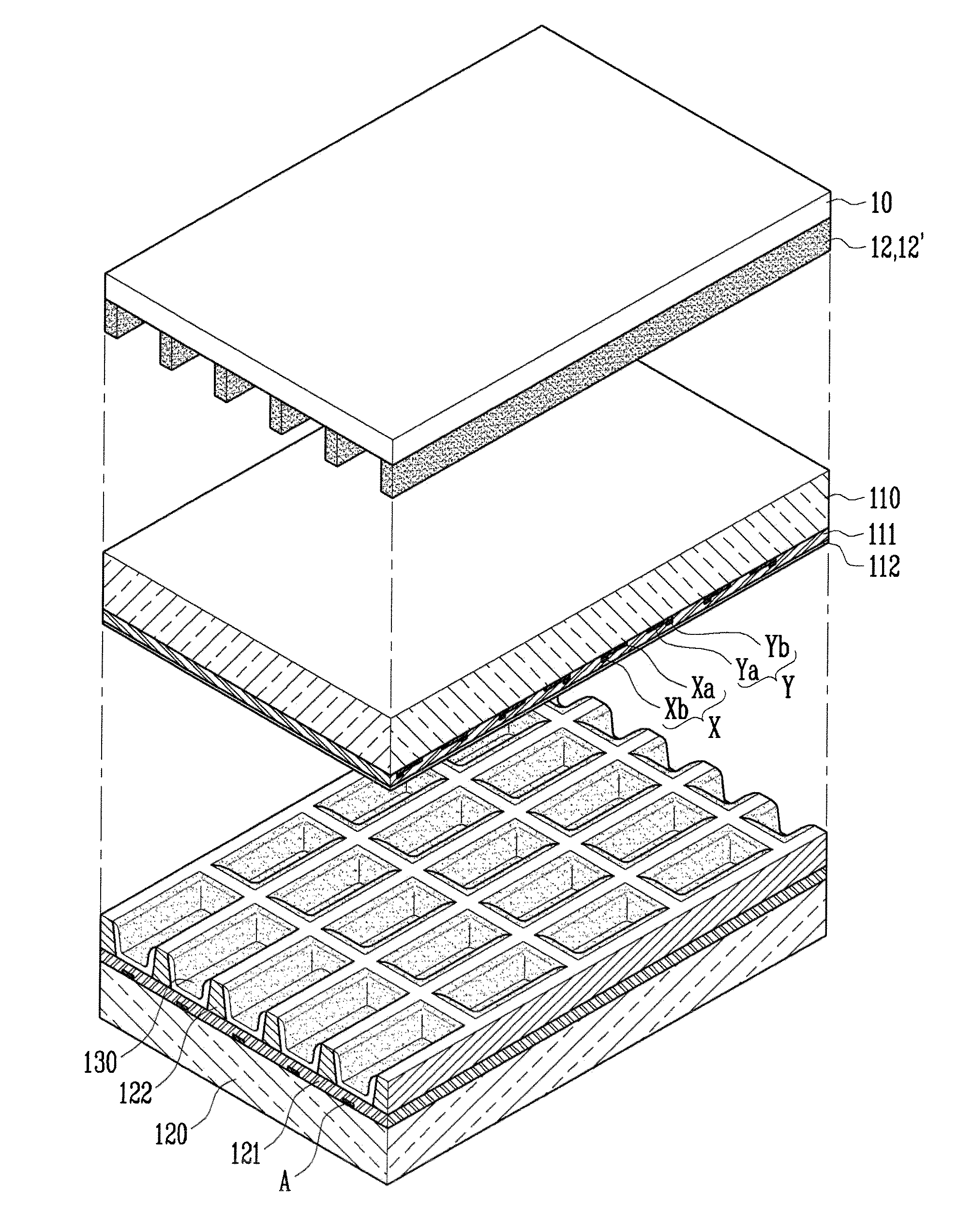
[0012]For the optical filter according to embodiments of the present invention, the light transmission of a stripe pattern made of a photochromic material may be changed according to the intensity of external light. The bright room contrast of the plasma display device may be improved since the reflection of external light may be minimized due to the low light transmission at an external light environment, and the luminance loss may be minimized due to the high light transmission under the external light-free condition.
[0013]Furthermore, the conventional optical filter has a disadvantage that viewing circumstances in a room with weak external light are restricted due to the fixed viewing angle. However, the optical filter according to embodiments of the present invention may have a more improved viewing angle range than the conventional optical filters since the photochromic pattern has a relatively higher light transmission at an indoor circumstance.

Problems solved by technology

However, the PDP emits electromagnetic waves and strong near-infrared rays in the process of generating plasma using a high voltage, and therefore the electromagnetic waves and the strong near-infrared rays adversely affect human health or cause abnormal operations in the electronic equipment.
The color purity may also be deteriorated by the near-infrared rays, which leads to the deteriorated image quality.

Method used


Image

  • Optical filter and plasma display device having the same
  • Optical filter and plasma display device having the same
  • Optical filter and plasma display device having the same

Examples


Embodiment Construction

[0019]In the following detailed description, when an element is referred to as being “on” another element, it can be directly on the element or be indirectly on the element with one or more intervening elements interposed therebetween. Also, when an element is referred to as being “connected to” another element, it can be directly connected to the element or be indirectly connected to the element with one or more intervening elements interposed therebetween. Hereinafter, like reference numerals refer to like elements.

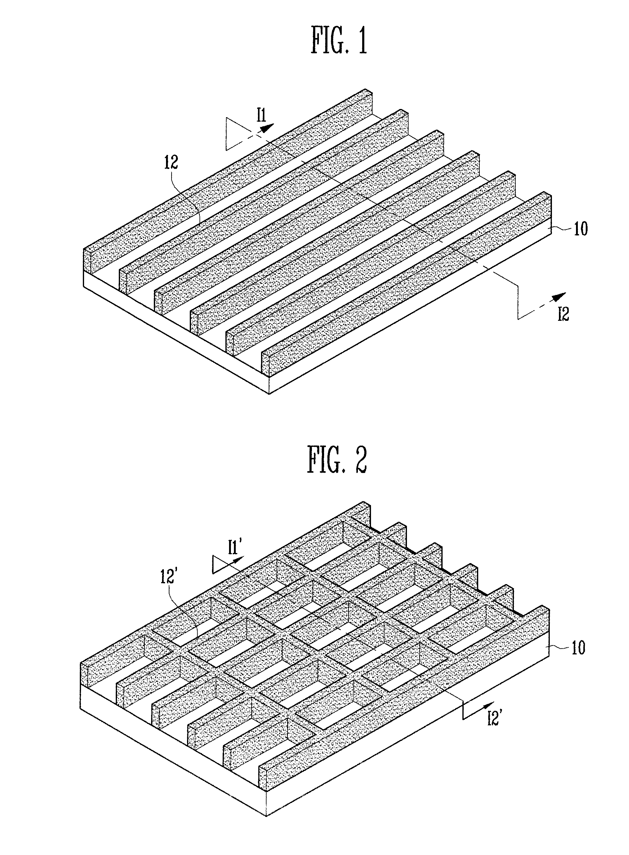
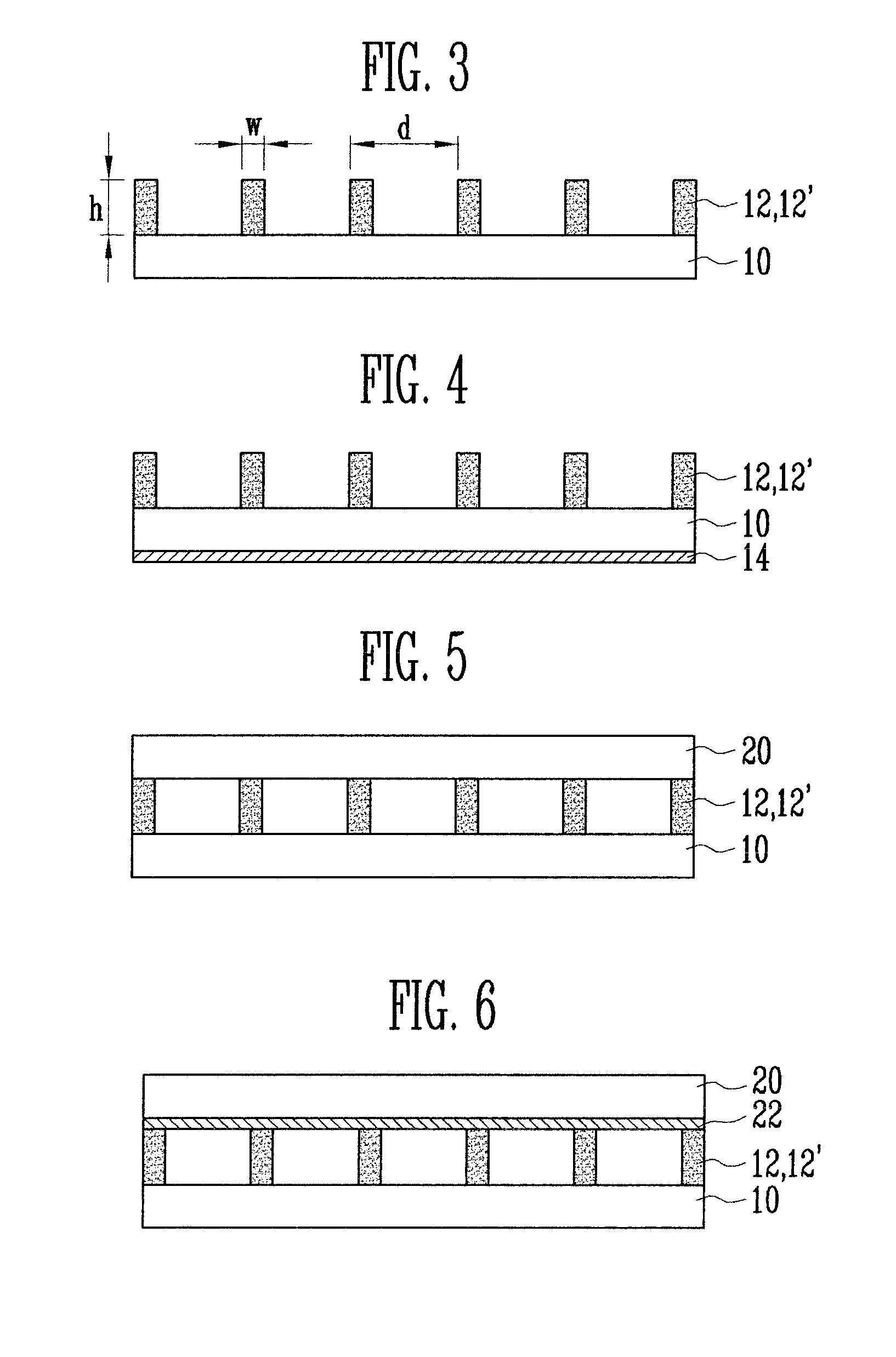
[0020]Referring to FIGS. 1 and 3, the optical filter according to one embodiment of the present invention includes a support layer 10, and a photochromic pattern 12 of stripes spaced apart on one surface of the support layer 10 and having a light transmission characteristic wherein light transmission is changeable according to the intensity of external light.

[0021]The support layer 10 is a base layer of the optical filter, and in an exemplary embodiment has high light t...


PUM


Abstract

An optical filter and a plasma display device having the same is provided. The optical filter includes a support layer. A photochromic pattern has pattern elements spaced apart on a surface of the support layer and has a light transmission characteristic wherein light transmission is changeable according to the intensity of external light.

Description

CROSS-REFERENCE TO RELATED APPLICATION[0001]This application claims priority to and the benefit of Korean Patent Application No. 10-2008-0051517, filed on Jun. 2, 2008, in the Korean Intellectual Property Office, the entire content of which is incorporated herein by reference.BACKGROUND[0002]1. Field of the Invention[0003]The present invention relates to flat panel displays, and, more particularly, to an optical filter used in a plasma display device.[0004]2. Discussion of Related Art[0005]A plasma display panel (PDP) is a flat panel display that displays characters or images by allowing a phosphor to emit light by means of plasma generated in the gas discharge. In recent years, the plasma display panel has emerged as a next-generation display device since it has inartificial color reproducibility, a short driving time and may be easily manufactured with longer-size and thinner scale than a cathode ray tube (CRT).[0006]However, the PDP emits electromagnetic waves and strong near-inf...

Claims


Application Information

Patent Timeline
IPC IPC(8): G09G3/10G02F1/03
CPCG02B5/208G02B5/20H01J11/44
Inventor HWANG, CHA-WONKWON, DO-HYUKLEE, SANG-MIBAEK, SEUNG-GOO
Owner SAMSUNG SDI CO LTD
Learn More