Switch-Off Time Regulation System for an Inverter for Driving a Lamp

a technology of inverter and lamp, which is applied in the direction of electric variable regulation, process and machine control, instruments, etc., can solve problems such as cross-sealed coils, and achieve the effect of optimizing the switch-on tim

Inactive Publication Date: 2009-12-03
OSRAM GMBH
View PDF8 Cites 9 Cited by
  • Summary
  • Abstract
  • Description
  • Claims
  • Application Information

AI Technical Summary

Benefits of technology

[0013]The invention is based on the fact which is known per se that the switch-on time of the switching element of the class E converter can have an effect on the power coupled into the lamp.
[0014]In the case of a DBD lamp, an optimized switch-on time can result, for example, in coupling-in of power which is improved by from 4 to 7%.

Problems solved by technology

If the switching element is open, a high induced voltage results across the storage coil owing to an abrupt change in current.

Method used


Image

  • Switch-Off Time Regulation System for an Inverter for Driving a Lamp
  • Switch-Off Time Regulation System for an Inverter for Driving a Lamp
  • Switch-Off Time Regulation System for an Inverter for Driving a Lamp

Examples


Embodiment Construction

[0009]The object of the invention is to specify an electronic ballast with a class E converter which is advantageous with respect to its output current.

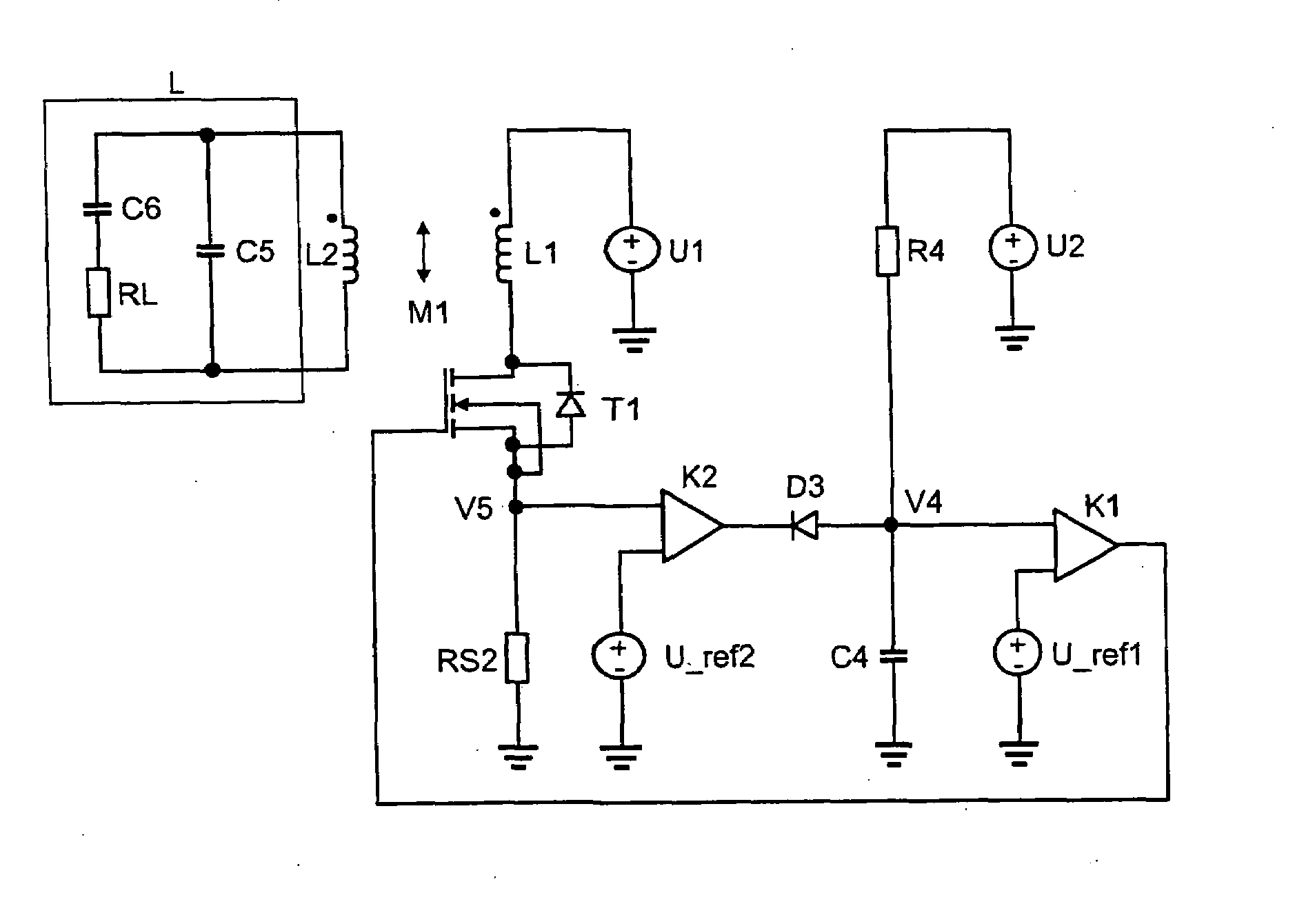
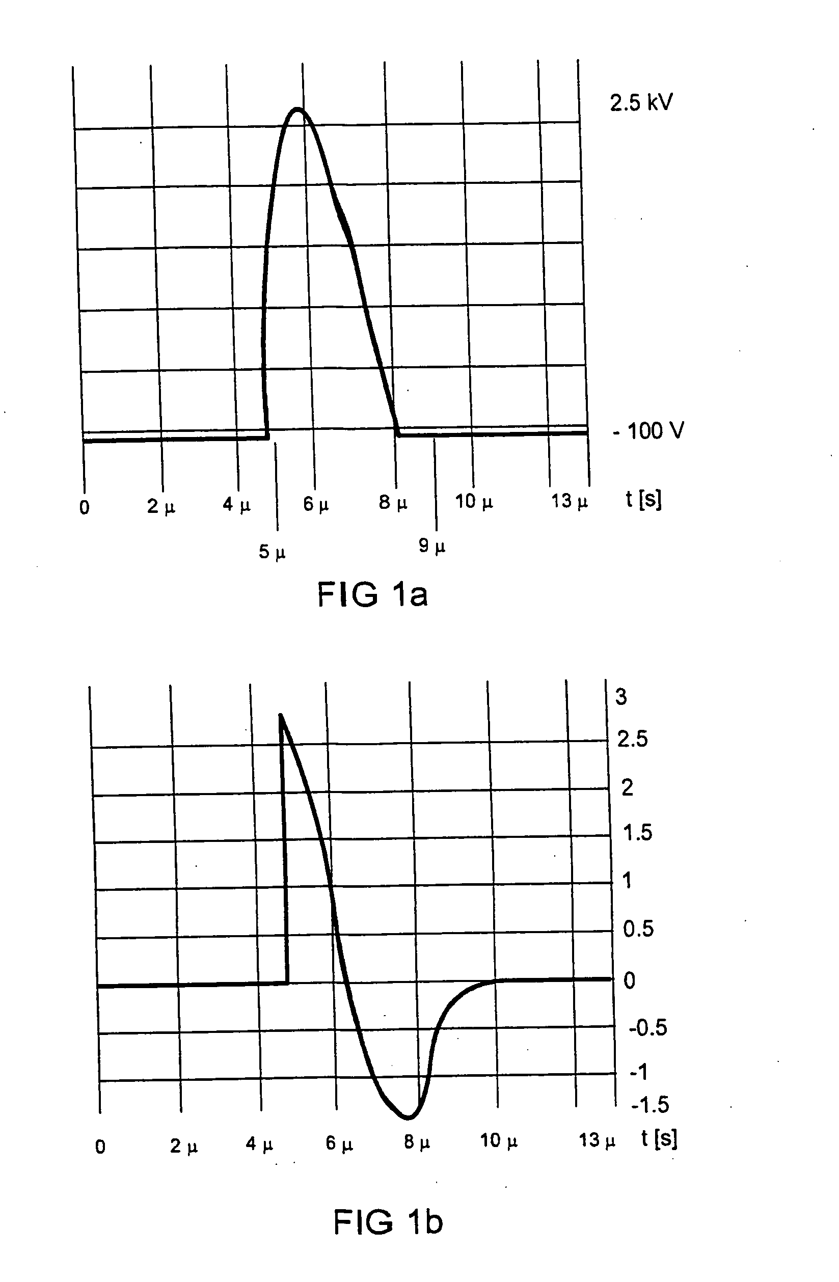
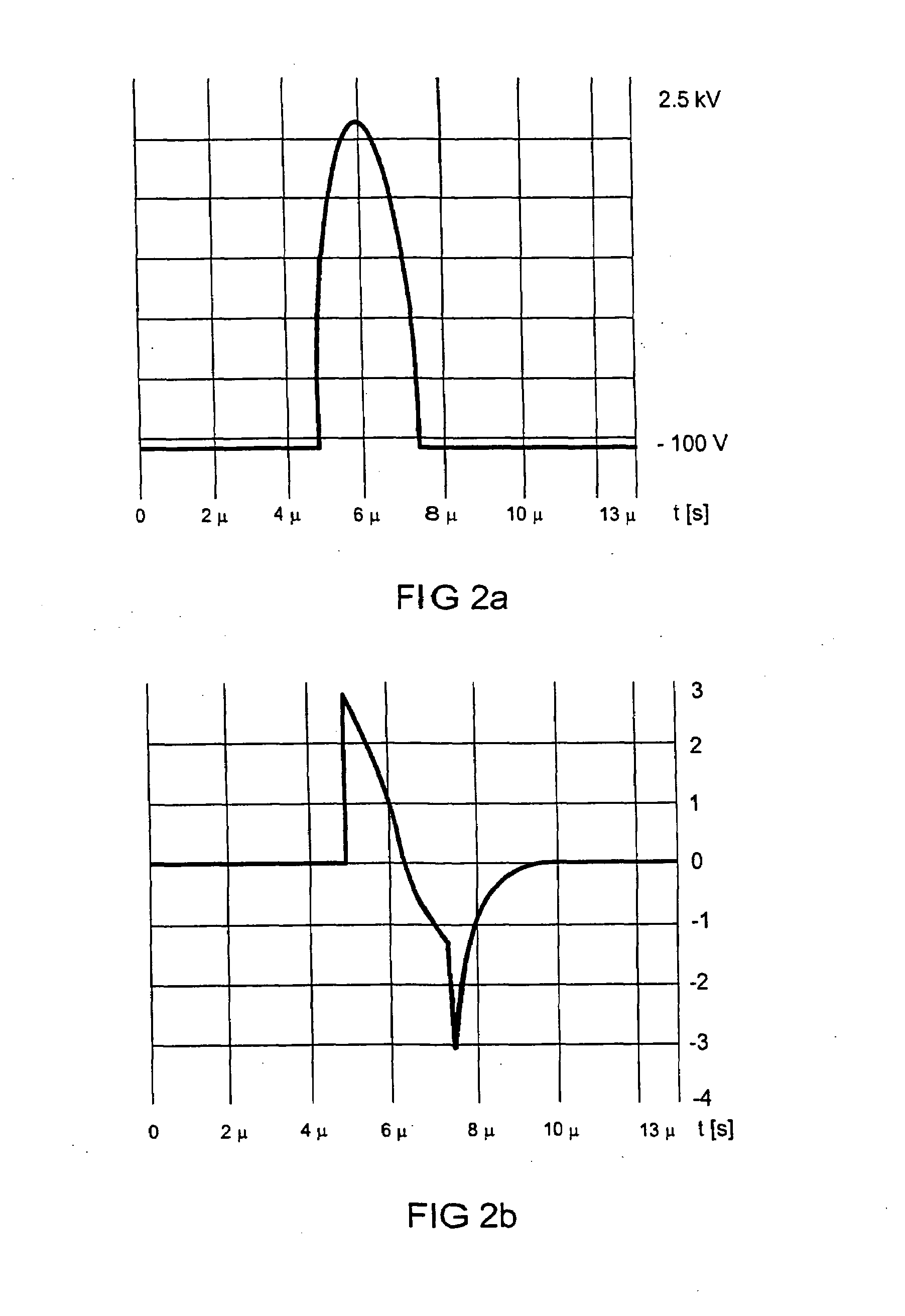
[0010]The object is achieved by an electronic ballast for operating a lamp with a class E converter having a switching element for supplying power to the lamp to be connected, an output current of the class E converter, when the lamp is connected and once the switching element has switched off, having a first and a second half-cycle of opposite polarity, characterized in that the electronic ballast has a measurement apparatus for measuring the output current and a regulating apparatus for setting a switch-on time of the switching element, the measurement apparatus being designed to determine a first output current value of the first half-cycle and a second output current value of the second half-cycle, and the regulating apparatus for setting the switch-on time being supplied a controlled variable based on the discrepancy between the...


PUM


Abstract

The present invention relates to an electronic ballast for operating a lamp (L) which has a Class E converter (T1, L1). When a lamp (L) is connected, the output current of the Class E converter (T1, L1) once a switching element (T1) of the Class E converter (T1, L1) has been switched off has a first and a second half-cycle of opposite polarity. The electronic ballast has a measurement apparatus for measuring the output current and a regulating apparatus for adjusting a switch-on time of the switching element. In this case, the measurement apparatus is designed to determine a first output current value of the first half-cycle and a second output current value of the second half-cycle, wherein the regulating apparatus for adjusting the switch-on time is fed a control variable based on the discrepancy between the two output current values.

Description

TECHNICAL FIELD[0001]The present invention relates to an electronic ballast for operating a lamp which has a class E converter.PRIOR ART[0002]Electronic ballasts for operating lamps are known in a wide variety of designs. There are various embodiments for different lamp types with in each case different rated powers or operating modes. A lamp connected for operation may be, for example, a discharge lamp, in particular a dielectric barrier discharge lamp.[0003]Electronic ballasts generate the lamp current necessary for operating the connected lamp. For this purpose, they have a converter. In principle, converters convert a power supply of the electronic ballast, for example the mains supply, into a power for operating the connected lamp. In this case, the output current and the output voltage of the converter are matched to the respective lamp type to be connected.[0004]For example, class E converters for operating dielectric barrier discharge lamps, so-called DBD lamps, convert a DC...

Claims


Application Information

Patent Timeline
Patent Type & Authority Applications(United States)
IPC IPC(8): H05B41/28
CPCH02M2001/0009Y02B20/22H05B41/2806H02M1/0009Y02B20/00H02M3/335H05B41/28
Inventor SOWA, WOLFRAM
Owner OSRAM GMBH
Why Eureka
Try Eureka