Dynamic range compression apparatus, dynamic range compression method, computer-readable recording medium, integrated circuit, and imaging apparatus

a compression apparatus and dynamic range technology, applied in the field of dynamic range compression apparatus, dynamic range compression method, integrated circuit, imaging apparatus, can solve the problems of not being able to perform dynamic processing and not being able to implement a function

Inactive Publication Date: 2009-12-03
PANASONIC CORP
View PDF4 Cites 23 Cited by
  • Summary
  • Abstract
  • Description
  • Claims
  • Application Information

AI Technical Summary

Benefits of technology

[0094]Through this, it is possible to achieve an imaging apparatus that achieves the same effects as the first aspect of the invention.
[0095]According to the present invention, it is possible to provide a dynamic range compression apparatus, a dynamic range compression method, a program, an integrated circuit, and an imaging apparatus capable of obtaining an image signal compressed at the full output range based

Problems solved by technology

For this reason, it is not capable of dynamic processing, and cannot implement a function for linking kne

Method used


Image

  • Dynamic range compression apparatus, dynamic range compression method, computer-readable recording medium, integrated circuit, and imaging apparatus
  • Dynamic range compression apparatus, dynamic range compression method, computer-readable recording medium, integrated circuit, and imaging apparatus
  • Dynamic range compression apparatus, dynamic range compression method, computer-readable recording medium, integrated circuit, and imaging apparatus

Examples


first embodiment

[0116]A D-range compression apparatus 1000, which is a first embodiment of the present invention, will be described with reference to FIGS. 7, 8A, and 8B.

[0117]

[0118]FIG. 7 is a block diagram illustrating the configuration of the D-range compression apparatus 1000 according to the first embodiment of the present invention.

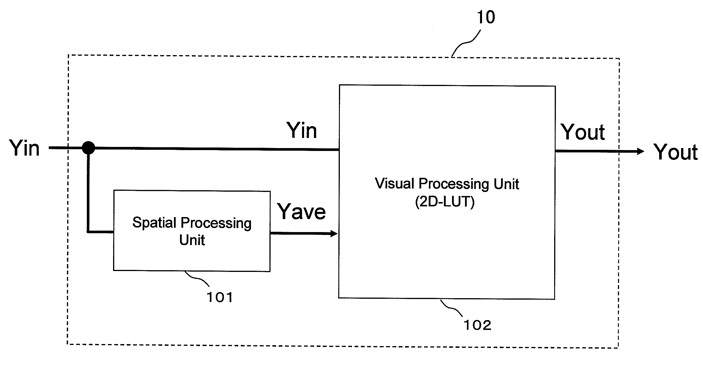
[0119]As shown in FIG. 7, the D-range compression apparatus 1000 according to the first embodiment of the present invention includes a peak detection unit 20 that detects the peak value Pin within an image formed by an image signal Yin (within an image formed by the image signal) and a pre-compression unit 30 that dynamically compresses the D-range of the image signal Yin to within the maximum input D-range of a visual processing unit 102 using the peak value Pin. The D-range compression apparatus 1000 also includes a visual processing apparatus 10 that performs visual processing on an output signal Yin′ outputted by the pre-compression unit 30 and an amplification...

second embodiment

[0162]In the first embodiment of the present invention, the pre-compression unit 30 and the amplification unit 40 performed control using only the peak value Pin; however, in a second embodiment of the present invention, a D-range compression apparatus 2000 performs control using the surrounding average luminance signal Yave in addition to the peak value Pin, thereby making it possible to maintain the contrast (the contrast of the processed image) during the pre-compression processing and amplification processing as well. This D-range compression apparatus 2000 will be described using FIGS. 9 to 12B.

[0163]

[0164]FIG. 9 is a block diagram illustrating the configuration of the D-range compression apparatus 2000 according to the second embodiment of the present invention.

[0165]As shown in FIG. 9, the D-range compression apparatus 2000 according to the second embodiment of the present invention includes a peak detection unit 20 that detects the peak value Pin within an image formed by an...

third embodiment

[0213]The D-range compression apparatus 2000 according to the second embodiment of the present invention is configured so that the pre-compression processing is not performed on the surrounding average luminance signal Yave; however, with a D-range compression apparatus 3000 according to a third embodiment of the present invention, the D-ranges of two inputs signals of a two-dimensional LUT in the visual processing unit 102 are aligned by performing pre-compression processing on the input signal of the spatial processing unit 101, thereby making it possible to organize the look-up table data of the two-dimensional LUT as a square matrix. The present embodiment will be described using FIG. 13.

[0214]FIG. 13 is a block diagram illustrating the configuration of the D-range compression apparatus 3000 according to the third embodiment of the present invention.

[0215]As shown in FIG. 13, the D-range compression apparatus 3000 according to the third embodiment of the present invention is con...


PUM


Abstract

A dynamic range (D-range) compression apparatus that uses a look-up table (LUT) is capable of dynamic compression that compresses the peak input value to the full output range, even when image signals with variable D-ranges are inputted.
According to this D-range compression apparatus, D-range compression processing that places the D-range of the image signal within a predetermined output D-range is performed by the visual processing unit converting the tone of the image signal in accordance with the surrounding average luminance signal. Furthermore, with this D-range compression apparatus, the image signal is amplified in accordance with amplification input/output conversion characteristics determined based on the peak value in the image detected by the peak detection unit, and therefore it is possible to perform a dynamic amplification processing in accordance with the peak value so that the D-range of the image signal outputted from the visual processing unit becomes a predetermined output D-range.

Description

[0001]This application claims priority to Japanese Patent Application No 2008-142967 filed on May 30, 2008, the entire disclosure of which is hereby incorporated herein by reference.BACKGROUND OF THE INVENTION[0002]1. Field of the Invention[0003]The present invention relates to a dynamic range compression apparatus, a dynamic range compression method, a program, an integrated circuit, and an imaging apparatus, and particularly relates to a dynamic range compression apparatus, dynamic range compression method, program, integrated circuit, and imaging apparatus in which an image signal with a variable dynamic range is inputted.[0004]2. Description of the Related Art[0005]Imaging apparatuses, such as digital cameras that shoot still images and digital video cameras that shoot videos, use an optical system to control exposure, and use a CCD image sensor, a CMOS image sensor, or the like to convert the image formed by the optical system into an electrical signal through photoelectric con...

Claims


Application Information

Patent Timeline
IPC IPC(8): H04N5/228G06K9/36
CPCH04N5/235H04N5/20H04N23/70
Inventor SATO, DAISUKEYAMASHITA, HARUOITO, TAKESHI
Owner PANASONIC CORP
Why Eureka
Try Eureka