Luminaire and method of operation

a technology of optical luminaires and halogen lamps, applied in the field of optical luminaires, can solve the problems of short life span of halogen mr-16 lamps producing 300 lumens and poor luminous efficacy

Active Publication Date: 2009-12-03
LIGHTING SCI GROUP
View PDF19 Cites 65 Cited by
  • Summary
  • Abstract
  • Description
  • Claims
  • Application Information

AI Technical Summary

Benefits of technology

[0021]FIG. 10 is a schematic side view illustration of height along a short

Problems solved by technology

A typical 20 W halogen MR-16 lamp producing 300 lumens has a

Method used


Image

  • Luminaire and method of operation
  • Luminaire and method of operation
  • Luminaire and method of operation

Examples


Embodiment Construction

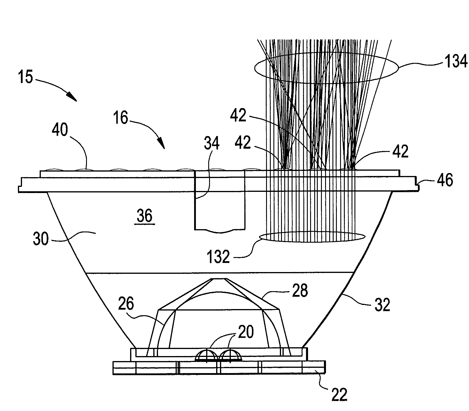
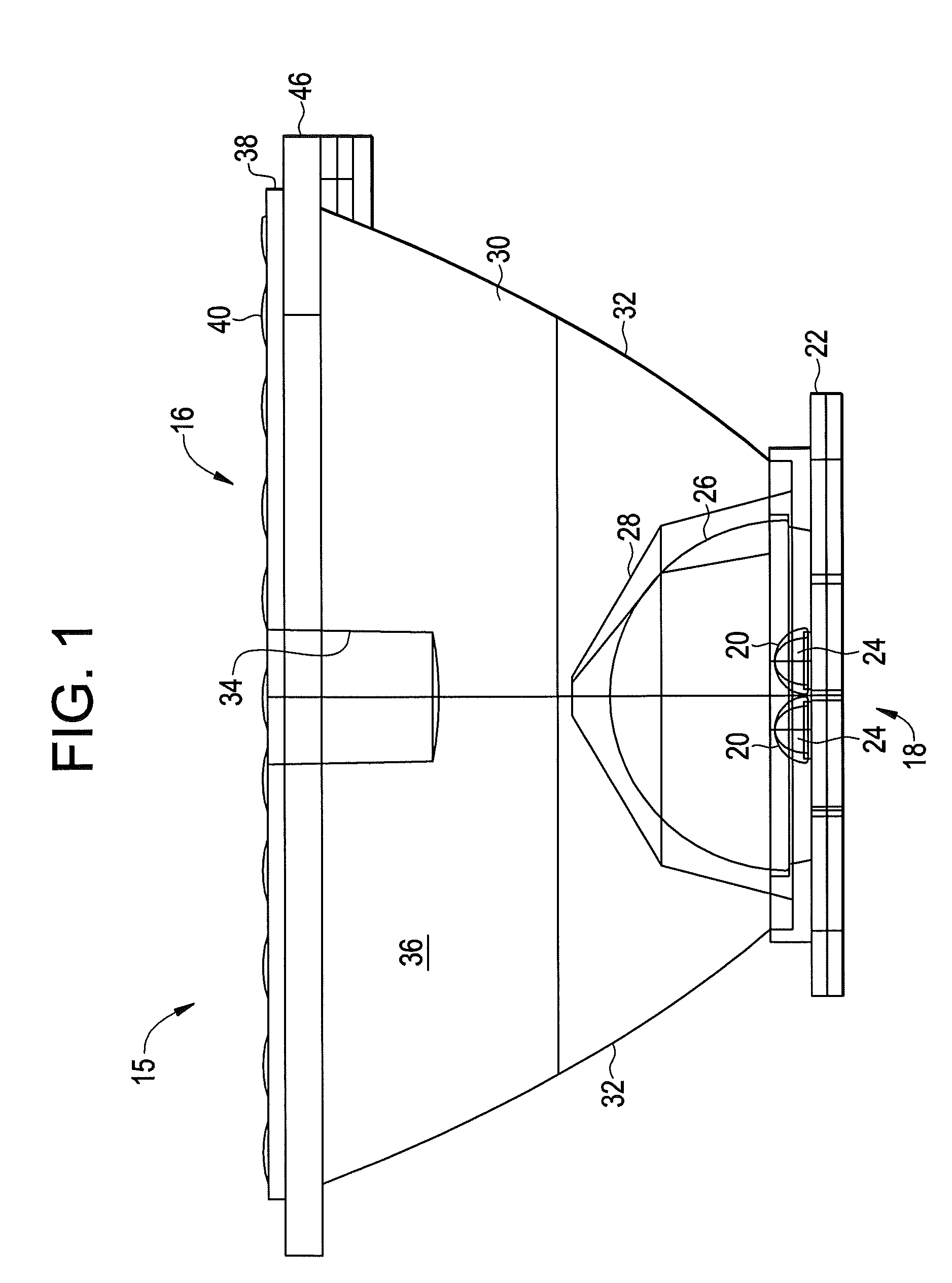
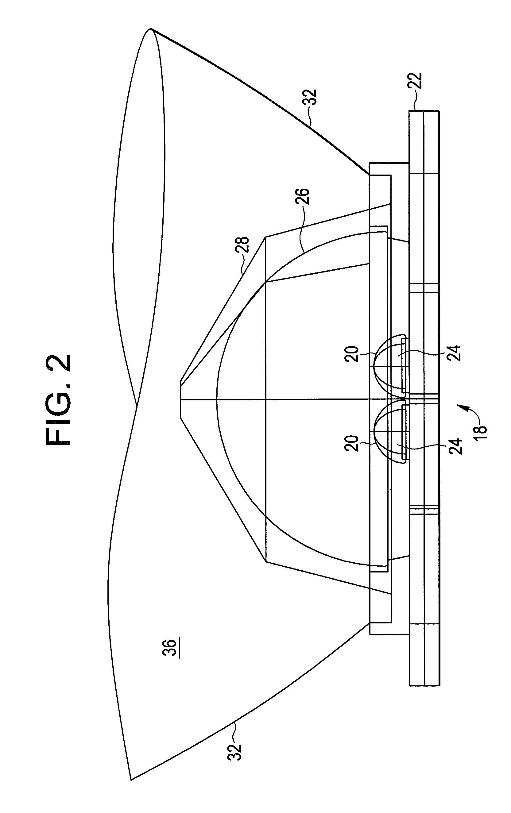
[0030]Embodiments of the present invention provide a luminaire that collimates light from an LED light source and disperses the light using a lenslet feature geometry called a “wisp lenslet”. A plurality of wisp lenslets is distributed throughout the cross-section of a collimated light beam. Each wisp lenslet slightly disperses and twists a bundle of light rays through refraction. The shape of the lenslet is arranged to refract individual rays of light to form a light ray bundle having a twisted profile upon exiting the luminaire. This refractive dispersion induced by the wisp lenslets provides advantages in the: (1) lessening the imaging of the light emitters; (2) lessening caustics in the collimated light beam caused by surface imperfections in the reflective or refractive optics; and (3) lessening the spatial light inconsistencies in the collimated light-beam, i.e., improving the color and / or intensity uniformity of the emitted light.

[0031]The twist profile is produced by the ref...


PUM


Abstract

A luminaire and a method of operating a luminaire is provided. The luminaire includes a light source emitting a plurality of light rays. A collimation device is arranged to receive a portion of light from the light source and transmits the portion of light through an exit aperture towards an illuminated area. The exit aperture includes a planar portion and at least one lenslet formed thereon. The lenslet is arranged having a first profile and a second profile, where the portion of light is refracted on a plurality of angles to form a twisted profile by the lenslet.

Description

CROSS REFERENCE TO RELATED APPLICATIONS[0001]This application claims priority to U.S. Provisional Application Ser. No. 61 / 056762 entitled “Light Dispersion Device for MR-16 Replacement” filed on May 28, 2008 which is incorporated herein by reference in its entirety.BACKGROUND OF THE INVENTION[0002]The subject matter disclosed herein relates to optical luminaires for generating light and in particular to a luminaire that eliminates die imaging caustics such as undesirable non-uniform concentrations of light, and improves spatial uniformity by using means for twisting a profile of a bundle of light rays.[0003]Lighting devices, such as incandescent or halogen sources for example, are used in many retail and product display venues due to the high light directionality and high color rendering index (“CRI”) they can achieve. These lighting devices use a standard receptacle, such as MR-16 for example, to receive a light source. The designation MR-16 stands for “Multifaceted Reflector” wher...

Claims


Application Information

Patent Timeline
IPC IPC(8): F21V13/04F21V5/04
CPCF21V5/04F21V7/0091G02B3/02G02B3/0037G02B3/0043F21Y2101/02F21Y2115/10
Inventor BAILEY, EDWARD
Owner LIGHTING SCI GROUP
Why Eureka
Try Eureka