Wireless communication apparatus and wireless communication method

a wireless communication and wireless communication technology, applied in data switching networks, synchronisation arrangements, frequency-division multiplexes, etc., can solve the problems of limited efficiency improvement, achieve effective increase of transmission capacity, improve system transmission capacity, and improve transmission capacity

Active Publication Date: 2009-12-03
PANASONIC CORP
View PDF27 Cites 36 Cited by
  • Summary
  • Abstract
  • Description
  • Claims
  • Application Information

AI Technical Summary

Benefits of technology

[0032]The first aspect of the present invention can improve the transmission capacity by realizing concurrent transmission through a plurality of links without providing a centralized-control station. Also, since each terminal apparatus autonomously judges whether concurrent transmission is available and controls the transmission timing, it is possible to realize concurrent transmission even in a structure without access points, such as an ad-hoc structure. Furthermore, since time for concurrent transmission is not limited, it is possible to more effectively increase the transmission capacity.
[0033]The second aspect of the present invention can improve the transmission capacity of the system as a whole, because the wireless communication apparatus performs concurrent transmission based on the CIR, even to a terminal exiting in a range within which a signal from an interference source is reachable with an unignorable strength. Even if the CIR is insufficient in a normal reception status, it is possible to improve the transmission capacity more, because the wireless communication apparatus performs interference reduction by controlling the interference reduction function and increase the CIR, which enables the concurrent transmission. In addition, since each terminal apparatus autonomously judges whether concurrent transmission is available and controls the transmission timing, it is possible to realize concurrent transmission even in a structure without a control station and a base station, such as an ad-hoc structure.

Problems solved by technology

Therefore, the technique of the Patent Document 2 has a problem that there is little chance of realizing the concurrent transmission, and improvement of the efficiency is limited.

Method used


Image

  • Wireless communication apparatus and wireless communication method
  • Wireless communication apparatus and wireless communication method
  • Wireless communication apparatus and wireless communication method

Examples


first embodiment

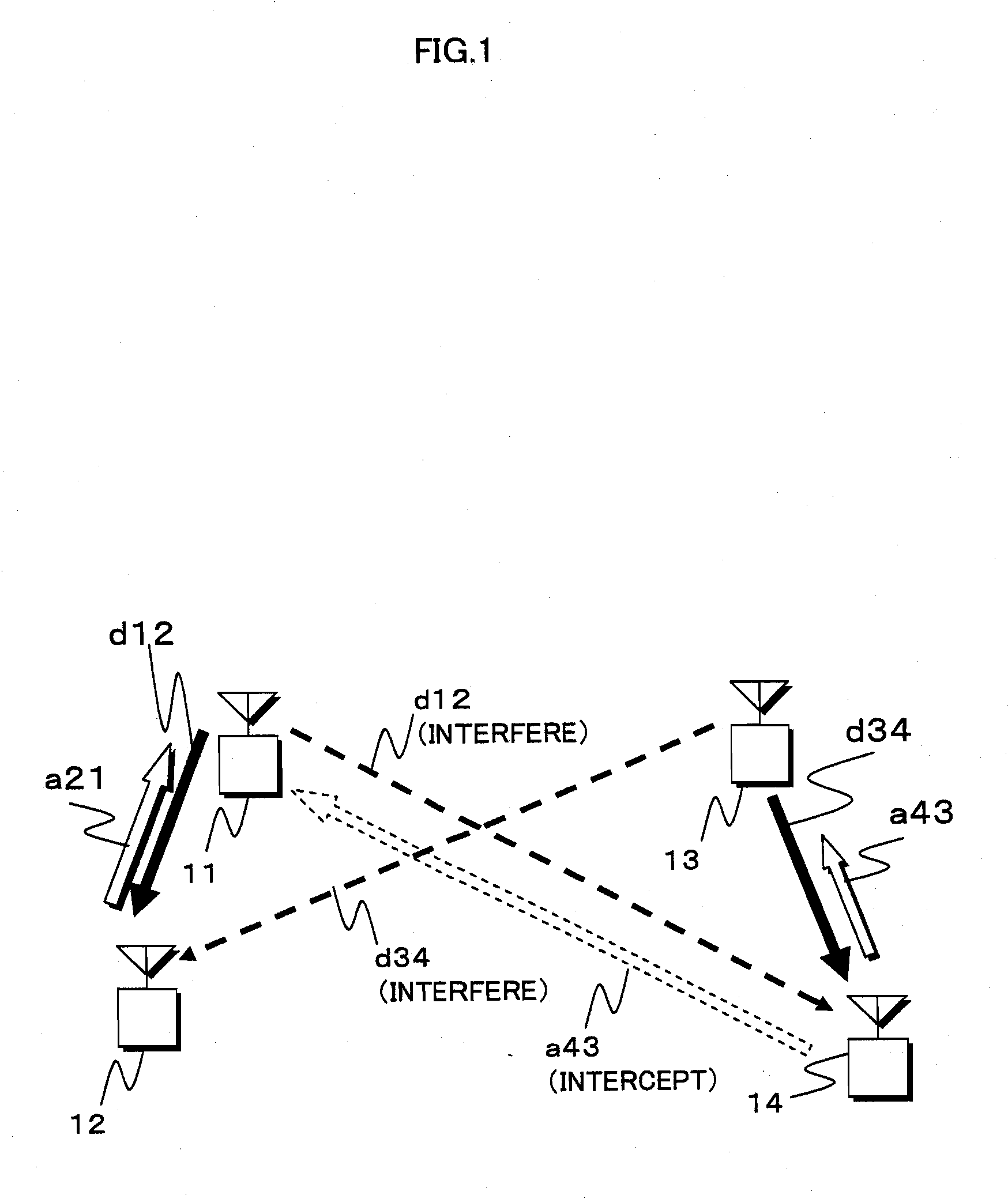
[0108]FIG. 1 is a conceptual diagram of a wireless communication system pertaining to the first embodiment of the present invention. In FIG. 1, the reference letters 11, 12, 13 and 14 represent wireless stations. The wireless station 11 communicates with the wireless station 12, and the wireless station 13 communicates with the wireless station 14. The reference letter d12 represents a data packet transmitted by the wireless station 11 to the wireless station 12. The reference letter d34 represents a data packet transmitted by the wireless station 13 to the wireless station 14. The reference letter a21 represents an ACK packet returned by the wireless station 12 to the wireless station 11 as receipt acknowledgement. The reference letter a43 represents an ACK packet returned by the wireless station 14 to the wireless station 13 as receipt acknowledgement.

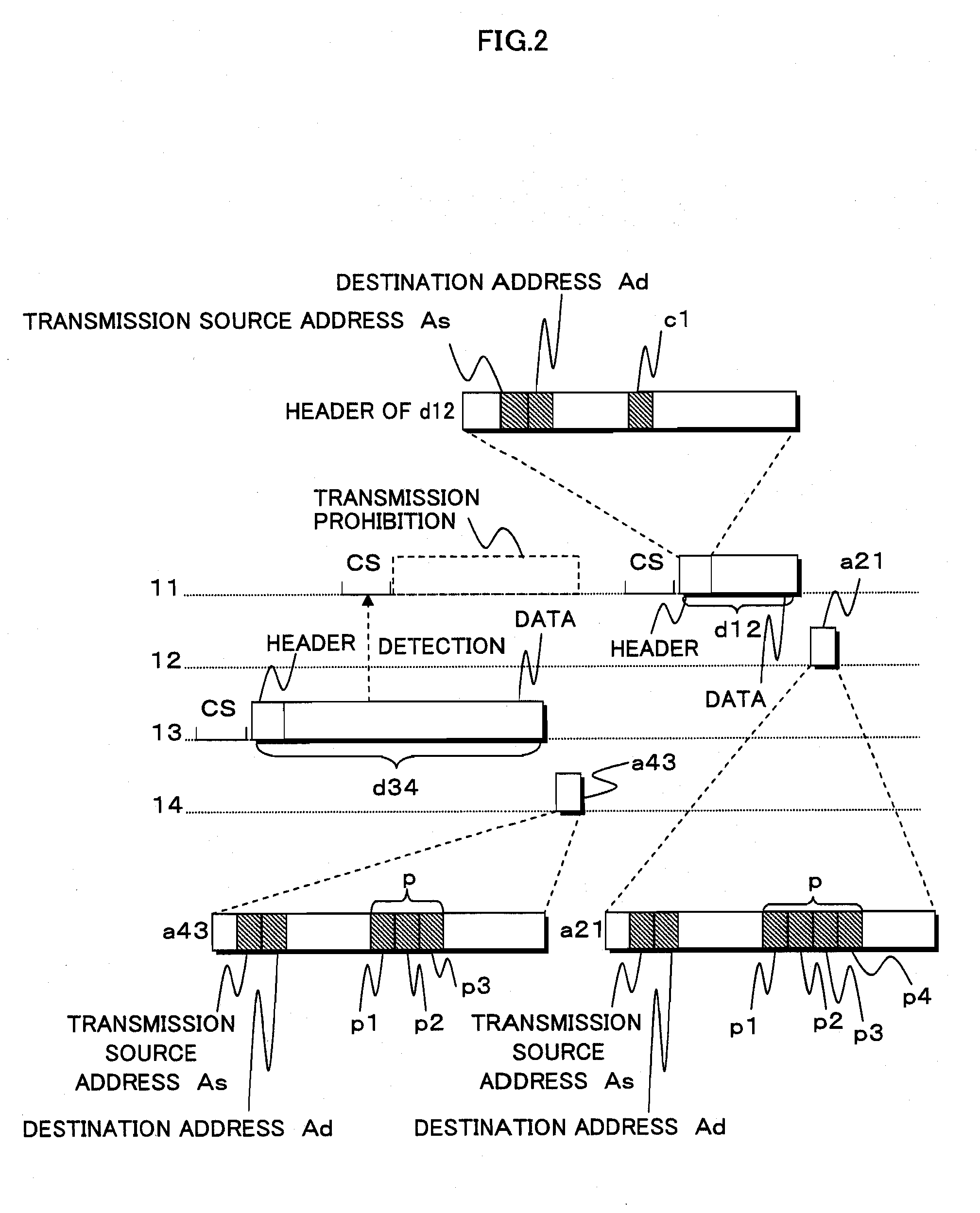
[0109]FIG. 2 shows a transmission sequence based on a CSMA technique at a time before concurrent data packet transmission is starte...

second embodiment

[0162]FIG. 9 shows a concept of a wireless communication system pertaining to the second embodiment. In FIG. 9, reference letters 211, 212, 213 and 214 represent wireless stations. The wireless station 211 communicates with the wireless station 212, and the wireless station 213 communicates with the wireless station 214. The reference letter d212 represents a data packet transmitted by the wireless station 211 to the wireless station 212. The reference letter d234 represents a data packet transmitted by the wireless station 213 to the wireless station 214. The reference letter a221 represents an ACK packet returned by the wireless station 212 to the wireless station 211 as receipt acknowledgement. The reference letter a243 represents an ACK packet returned by the wireless station 214 to the wireless station 213 as receipt acknowledgement. Among these wireless stations, at least the wireless station 212 has an interference reduction mechanism that reduces the strength of a reference ...

third embodiment

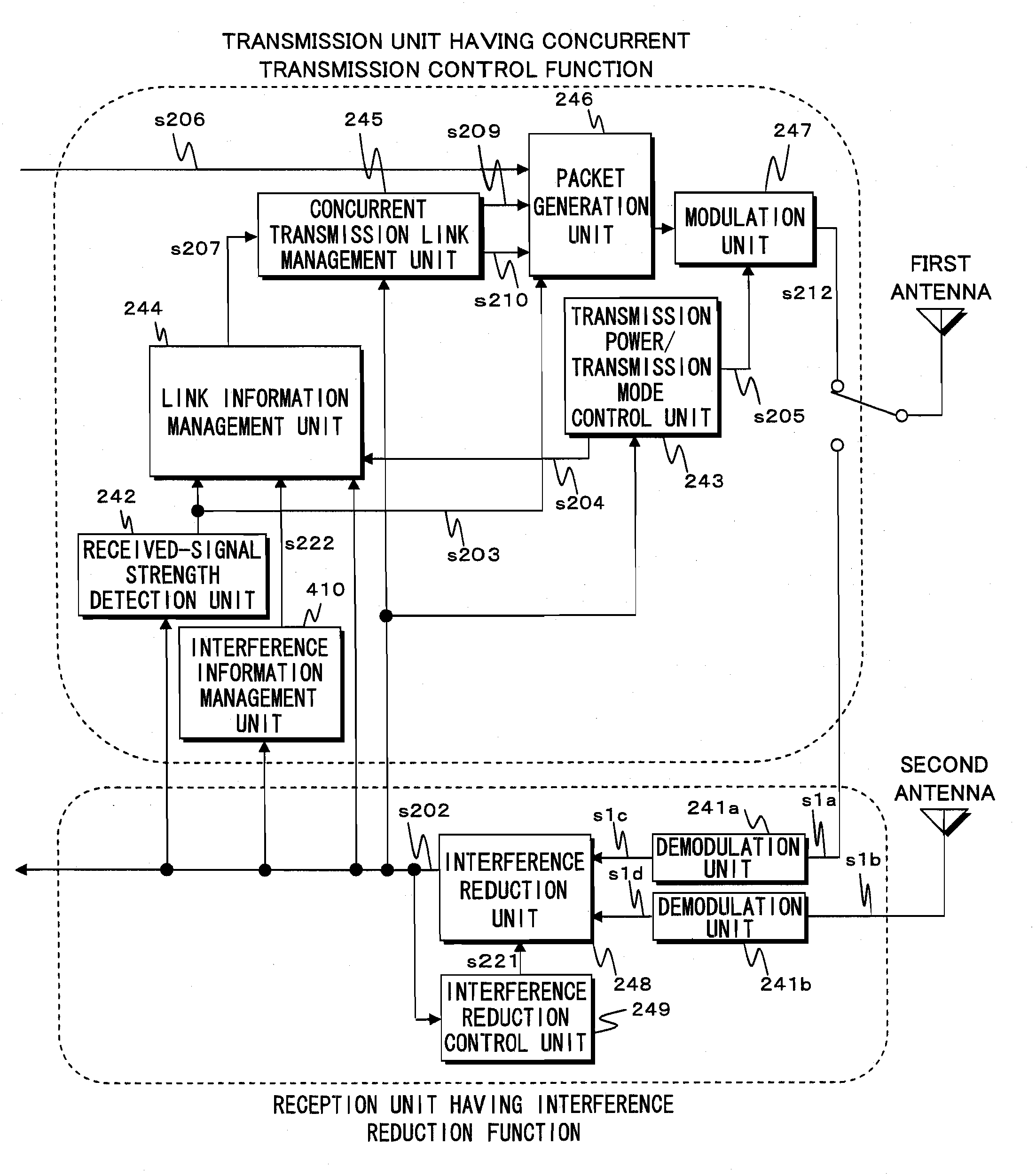
[0226]FIG. 18 shows an example structure of a wireless communication apparatus pertaining to the third embodiment of the present invention. Most part of FIG. 18 is the same as the structure shown in FIG. 13. However, FIG. 18 is different from FIG. 14 in that a given-interference judgment unit 412 is added, and the transmission power / transmission mode control unit 431 has an additional function compared to the transmission power / transmission mode control unit 243 of FIG. 13. Other components and operations are the same as those of the second embodiment. Accordingly, the details thereof are not explained here.

[0227]The given-interference judgment unit 412 monitors the decoded data s202 to check whether the communication between the interference station and its communication party is normally performed, and notifies the transmission power / transmission mode control unit 431 of the results. In the sequence of FIG. 10, when the ACK packet a243 of the wireless station 214 is received, the ...


PUM


Abstract

When communicating with a second wireless station, a first wireless station judges, based on link-related information received form the second wireless station and link-related information extracted from a signal transmitted by a fourth wireless station, whether a transmission link from the third wireless station to the fourth wireless station and a transmission link from the first wireless station to the second wireless station can be concurrently established without interference with each other. If judging affirmatively, the first wireless station transmits a signal to the second wireless station in synchronization with a signal transmitted by the third wireless station to the fourth wireless station. Preferably, when the first wireless station having a concurrent transmission control function communicates with the second wireless station having a interference reduction function, the first wireless station controls the interference reduction function of the second wireless station based on the link-related information received from the second wireless station and interference information, such that the transmission link from the third wireless station to the fourth wireless station and the transmission link from the first wireless station to the second wireless station can be established at the same time without interference with each other. If judging that the concurrent transmission is available, the first wireless station transmits a signal to the second wireless station according to a timing that overlaps transmission of a signal from the third wireless station to the fourth wireless station.

Description

TECHNICAL FIELD[0001]The present invention relates to a wireless communication apparatus and a wireless communication method that are capable of performing data transmission / reception through a plurality of links at the same time in a wireless communication system in which a plurality of links coexist, so that high space-use efficiency is achieved. Note that the term “link” in this Specification means a transmission of data from a wireless station as a transmitter to a wireless station as a receiver.BACKGROUND ART[0002]Conventionally, in wireless communication systems that perform packet wireless transmission such as wireless LAN systems, the access control method based on carrier sense (i.e. CSMA method) has been commonly used. For example, Non-patent Document 1 discloses a CSMA / CA method that uses, in addition to the carrier sense base on received-signal strengths, a request-to-send (RTS) packet and a clear-to-send (CTS) packet.[0003]The CSMA / CA method is aimed to avoid packet col...

Claims


Application Information

Patent Timeline
Patent Type & Authority Applications(United States)
IPC IPC(8): H04L12/26H04W74/08
CPCH04W56/002H04W74/0808H04W72/1205H04W72/12
Inventor URABE, YOSHIOMIYANAGA, KENJIANDO, KAZUHIROAPICHAICHALERMWONGSE, CHALERMPHOLMUKAI, TSUTOMU
Owner PANASONIC CORP
Why Eureka
Try Eureka