Developer Carrying Device and Image Forming Device

a developer carrying and image forming technology, applied in the direction of instruments, electrographic process devices, optics, etc., can solve the problems of unsuitable development, small charged amount, and negative charge of the developer, so as to prevent alteration of the property, facilitate development, and perform development more smoothly

Inactive Publication Date: 2009-12-03
BROTHER KOGYO KK
View PDF10 Cites 13 Cited by
  • Summary
  • Abstract
  • Description
  • Claims
  • Application Information

AI Technical Summary

Benefits of technology

[0012]As describe above, the developer circulates on the first carrying body, and only the small amount of developer corresponding to the supplied amount to the developer supply target is newly added to the first carrying body from the second carrying body. Therefore, almost all of the developer on the first carrying body is sufficiently charged positively by the frictional charge during circulation, and therefore variations of the charged state of the developer are small. Therefore, the sufficiently charged developer can be supplied to the developer supply target. Even if a cluster of developer is supplied from the second carrying body to the first carrying body, the added amount is limited, and such a cluster collapses while the cluster circulates on the first carrying body. That is, a cluster of developer can be prevented from reaching the developer supply target, and therefore the sufficiently charged developer can be supplied to the developer supply target.
[0013]Although the present invention is not limited to the configuration indicated below, the first electrode group may be continuously arranged to have a cylindrical shape. In this case, it becomes possible to circulate the developer on the first carrying body more smoothly.
[0014]A surface of the first electrode group may be made of material which charges the developer in a desired state. In

Problems solved by technology

For this reason, there is a possibility that the condition of the developer fluctuates and thereby development can not be performed suitably arises in the cases explained below.
Since the developer in the inside of such a cluster of developer can not be charged by fr

Method used


Image

  • Developer Carrying Device and Image Forming Device
  • Developer Carrying Device and Image Forming Device
  • Developer Carrying Device and Image Forming Device

Examples


Embodiment Construction

General Configuration of Laser Printer

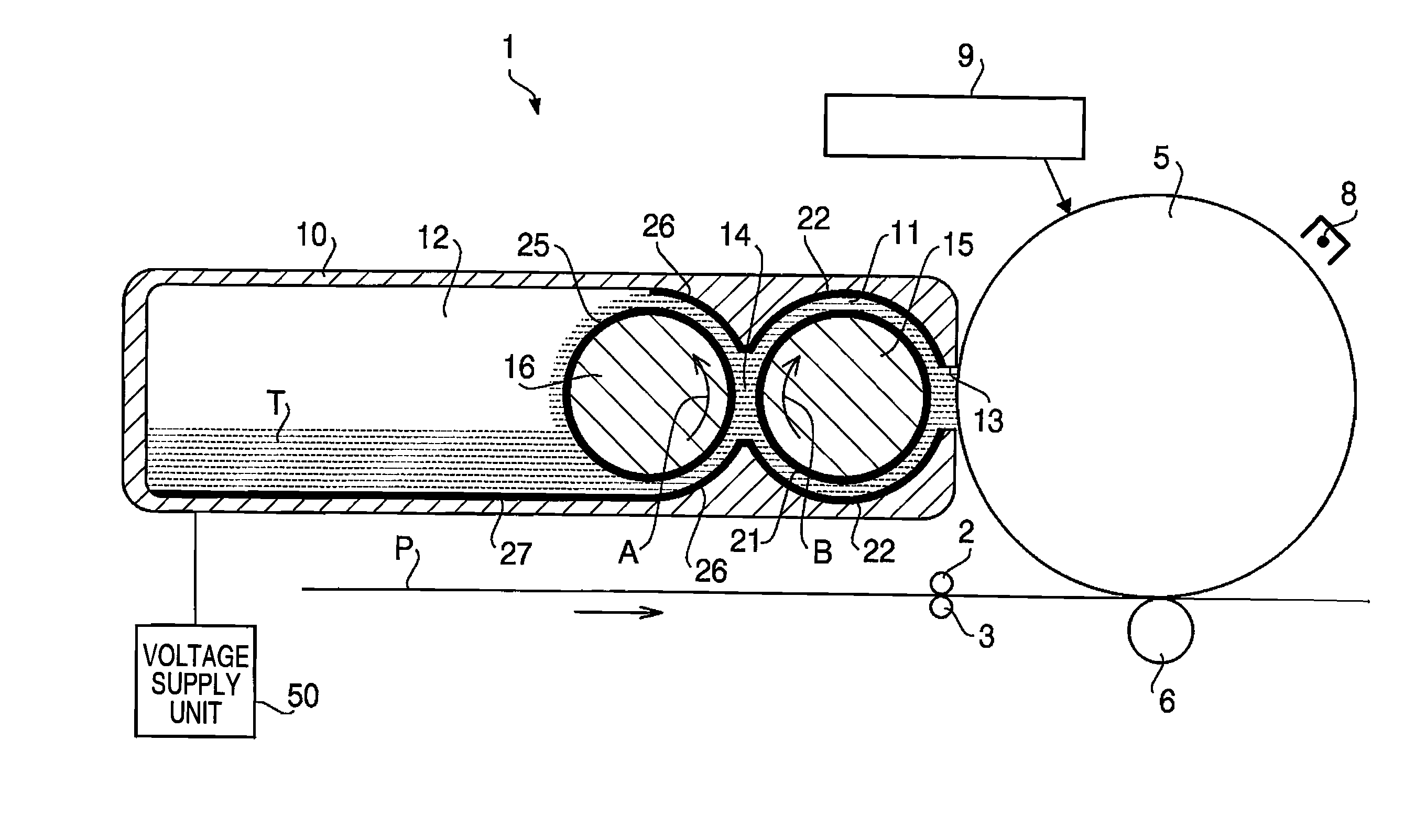
[0033]Hereafter, an embodiment according to the present invention will be described with reference to the accompanying drawings. FIG. 1 is an explanatory illustration for explaining main parts of a laser printer 1 according to the embodiment. It should be noted that the laser printer 1 configured to form an image by toner T on a surface of a sheet of paper P while carrying sheets of paper accommodated in a paper supply tray (not shown) one by one.

[0034]As shown in FIG. 1, the laser printer 1 includes registration rollers 2 and 3 controlled to properly hold the leading edge of the sheet of paper P supplied from a paper supply tray. The registration rollers 2 and 3 start to carry, at predetermined timing, the sheet of paper P held therebetween toward space between a photosensitive drum 5 and a transfer roller 6.

[0035]The photosensitive drum 5 is grounded, and, on the photosensitive drum 5, a photosensitive layer having a positive electrostatic pro...


PUM


Abstract

There is provided a developer carrying device, including a first carrying body having a first electrode group configured to from a traveling electric field while being applied a voltage sequentially and to circulate charged developer through a facing portion with respect to a developer supply target; and a second carrying body having a second electrode group configured to from a traveling electric field while being applied a voltage sequentially and to circulate the developer through a facing part with respect to the first electrode group so that the developer being carried is supplied to the first carrying body.

Description

[0001]This is a Continuation-in-Part of International Application No. PCT / JP2007 / 072807 filed Nov. 27, 2007, which claims priority from Japanese Patent Application No. 2006-324542 filed Nov. 30, 2006. The entire disclosure of the prior application is hereby incorporated by reference herein its entirety.BACKGROUND[0002]1. Technical Field[0003]Aspects of the present invention relate to a developer carrying device which carries charged developer through a traveling electric filed, and an image forming device having such a developer carrying device.[0004]2. Related Art[0005]Conventionally, various types of developer carrying devices configured to carry charged developer through use of a plurality of electrodes which form a traveling electric field when applied voltages in sequence have been proposed. For example, Japanese Patent Provisional Publication No. 2003-265982 discloses a developer carrying device which includes an opposed carrying substrate having a first electrode group carryi...

Claims


Application Information

Patent Timeline
IPC IPC(8): G03G15/08
CPCG03G15/0808G03G2215/0651G03G2215/0643G03G15/0818
Inventor MAEDA, MASATAKANISHIWAKI, KENJIRO
Owner BROTHER KOGYO KK
Why Eureka
Try Eureka