Online systems and methods for thermal inspection of parts

a technology of thermal inspection and parts, applied in liquid fuel engines, instruments, machines/engines, etc., can solve the problems of reducing film effectiveness and/or thermal performance, time-consuming technique, and ignoring local or individual features or holes that are out of specification, and achieve satisfactory thermal performance of cooled parts

Inactive Publication Date: 2009-12-03
GENERAL ELECTRIC CO
View PDF26 Cites 34 Cited by
  • Summary
  • Abstract
  • Description
  • Claims
  • Application Information

AI Technical Summary

Benefits of technology

[0005]In accordance with an embodiment of the invention, a thermal inspection method is provided. The method includes measuring a transient thermal response of a cooled part installed in a turbine engine, wherein the transient thermal response results from operation of the turbine engine. The method also includes using the transient thermal response to determine one or more of a flow rate of a fluid flowing through one or more film cooling holes in the cooled part during operation of the turbine engine, at least one heat transfer coefficient for one or more internal passages in the cooled part, and a combined thermal response for the cooled part. The method further includes comparing at least one of the flow rate, the at least one heat transfer coefficient, and the combined thermal response of at least a portion of the cooled part to at least one baseline value to determine whether a thermal performance of the cooled part is satisfactory.
[0006]In accordance with another embodiment of the invention, a thermal inspection method is provided. The method includes measuring multiple transient thermal responses of a respective number of cooled parts installed in a turbine engine, wherein the transient thermal responses result from operation of the turbine engine. The method also includes using the transient thermal responses to determine at least one of a respective flow rate of a fluid flowing through one or more film cooling holes on each of the cooled parts during operation of the turbine engine, at least one heat transfer coefficient for one or more internal passages in each of the cooled parts, and a respective combined thermal response for each of the cooled parts. The method also includes comparing at least one of the flow rates, the heat transfer coefficients and the combined thermal responses of at least a portion of each of the cooled parts to determine whether a respective thermal performance of each of the cooled parts is satisfactory.
[0007]In accordance with another embodiment of the invention, a system for thermal inspection of a cooled part installed in a turbine engine is provided. The system includes a thermal monitoring device configured to detect at least one surface temperature, either directly or indirectly, of the cooled part at multiple times corresponding to a transient thermal response of the cooled part, wherein the transient thermal response results from operation of the turbine engine. The system also includes a processor configured to determine based upon the transient thermal response one or more of a flow rate of a fluid flowing through one or more film cooling holes in the cooled part during operation of the turbine engine, at least one heat transfer coefficient for one or more internal passages in the cooled part and a combined thermal response for the cooled part. The processor is also configured to compare at least one of the flow rate, the at least one heat transfer coefficient, and the combined thermal response of at least a portion of the cooled part to at least one baseline value to determine whether a thermal performance of the cooled part is satisfactory.

Problems solved by technology

However, the technique is known to be time consuming resulting in a check of only selective film holes, groups of holes, or flow circuits.
Additionally, the technique has the propensity to overlook local or individual features or holes that are out of specification.
However, the aforementioned techniques are employed before the parts enter service and not during operation.
During operation, parts such as, but not limited to, airfoils with film holes and internal cooling cavities are subject to blockage from ingested debris by the engine or other damage resulting in diminished film effectiveness and / or thermal performance.
While internal damage may be seen during visual inspections offline, they cannot be visually detected online.

Method used


Image

  • Online systems and methods for thermal inspection of parts
  • Online systems and methods for thermal inspection of parts
  • Online systems and methods for thermal inspection of parts

Examples


Embodiment Construction

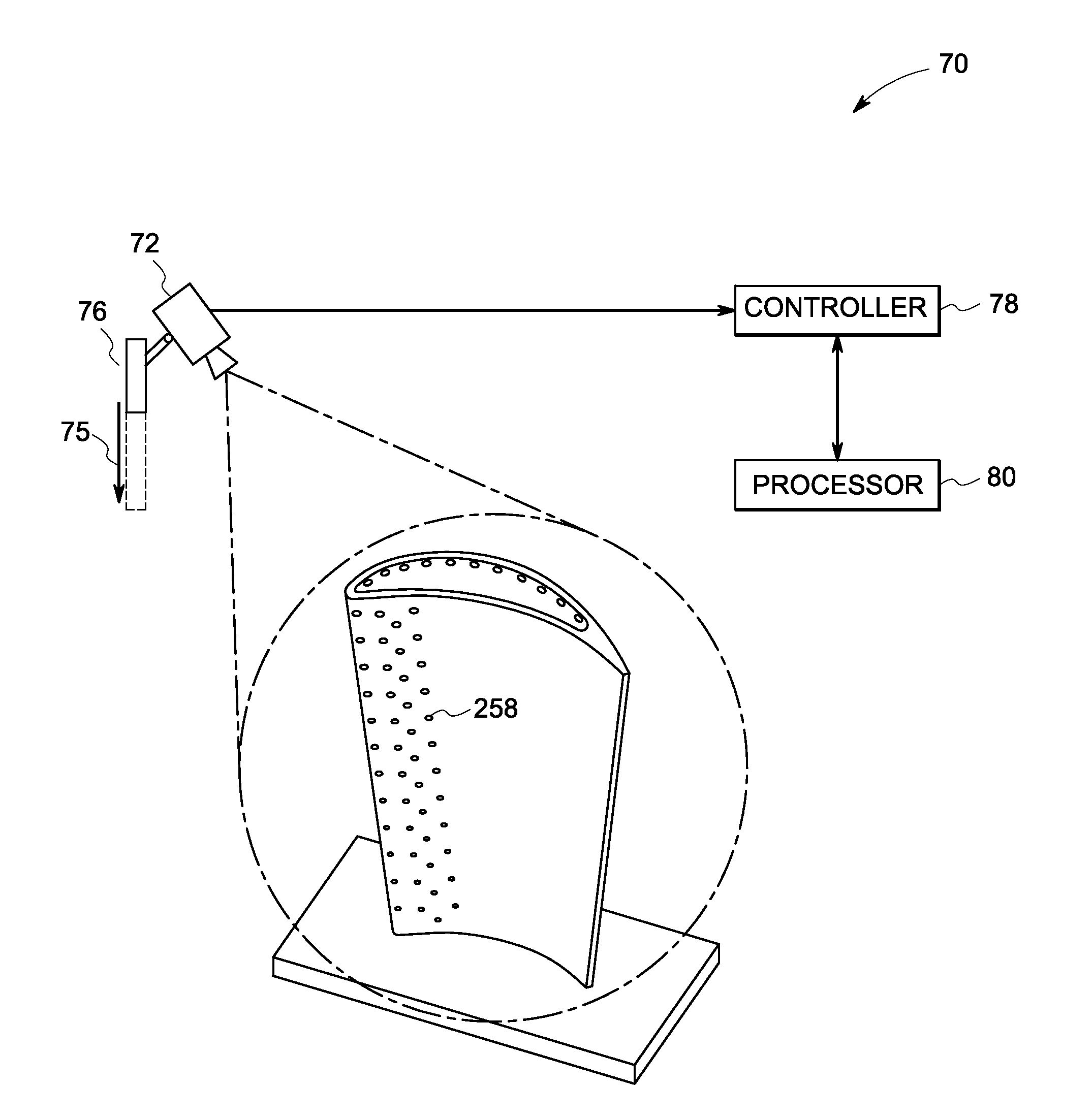
[0021]As described in detail below, embodiments of the invention are directed to online systems and methods for thermal inspection of one or more cooled parts during operation of an engine. Example ‘parts’ include equipment used in engine systems such as, but not limited to, turbine engines. As used herein, the term ‘online system and method’ refers to a system and method that inspects the parts during operation of an engine in a real environment such as, among others, a hot gas flowing over the part under real temperatures, real pressures and real hot gas characteristics. Further, the phrase “operation of an engine” should be understood to encompass any operation of the engine, including but not limited to start-up and steady state operation. As used herein, the term “cooled part’ refers to parts equipped with internal cooling passages and / or with film cooling holes and associated passages.

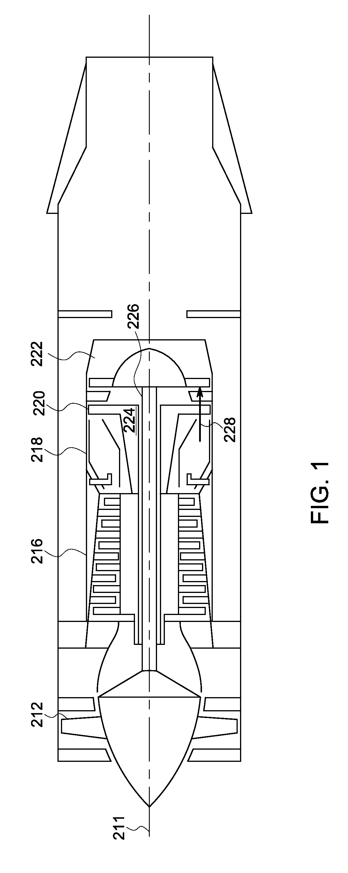
[0022]Turning to the drawings, FIG. 1 is an exemplary gas turbine engine 210 circumferentiall...


PUM


Abstract

A thermal inspection method is provided. The method includes measuring a transient thermal response of a cooled part installed in a turbine engine, wherein the transient thermal response results from operation of the turbine engine. The method also includes using the transient thermal response to determine one or more of a flow rate of a fluid flowing through one or more film cooling holes in the cooled part during operation of the turbine engine, at least one heat transfer coefficient for one or more internal passages in the cooled part, and a combined thermal response for the cooled part. The method further includes comparing at least one of the flow rate, the at least one heat transfer coefficient, and the combined thermal response of at least a portion of the cooled part to at least one baseline value to determine whether a thermal performance of the cooled part is satisfactory.

Description

BACKGROUND[0001]The invention relates generally to thermal inspection systems and methods and more specifically, to non-destructive thermal inspection of cooled parts during operation of the system.[0002]There are several techniques that are currently used for inspection of cooled parts for internal cavities. A commonly used technique is “flow checks”. A flow check measures a total flow through a part. The measurement is made for a group of film holes by blocking a remaining group of film holes or rows of holes. The process is repeated with various holes or passages blocked until all desired measurements have been made. Comparisons to either gauge measurements on reliable parts or to analytical models of flow circuits determines the acceptability of the parts. However, the technique is known to be time consuming resulting in a check of only selective film holes, groups of holes, or flow circuits. Additionally, the technique has the propensity to overlook local or individual features...

Claims


Application Information

Patent Timeline
Patent Type & Authority Applications(United States)
IPC IPC(8): F01D25/00G01F1/68
CPCG01F1/68F05B2260/80
Inventor ALLEN, JASON RANDOLPHBUNKER, RONALD SCOTT
Owner GENERAL ELECTRIC CO
Why Eureka
Try Eureka