Cooling tower of hydrodynamic draught fan

A hydraulic fan and cooling tower technology, applied in the field of cooling towers, can solve the problems of high water pressure energy consumption, low speed of fan blades, and failure to meet the cooling effect of cooling towers, so as to meet the requirements of improving industrial energy consumption and reducing The effect of fixed costs

Inactive Publication Date: 2011-09-14
张普妲 +1
View PDF7 Cites 1 Cited by
  • Summary
  • Abstract
  • Description
  • Claims
  • Application Information

AI Technical Summary

Problems solved by technology

The efficiency of Pelton water turbine is not high, it needs high water pressure to rotate, so to realize this patent, high water pressure and excess water volume must be used to waste energy. This patent has no practicality, and there is no product due to failure.
It was applied for on October 29, 1998, and the publication number is CN1221103A. The energy-free cooling tower also does not follow the condition that the energy required to drive the fan blades should meet the existing energy inside the circulating water flow, and cannot be applied to all cooling towers.
[0003] The advantage of the above-mentioned hydraulic air intake cooling tower in the prior art is that the water turbine is driven by circulating water, and the output shaft of the water turbine drives the fan blades to rotate, which can save energy by saving the motor, but it still has the disadvantage that it does not follow the energy required to drive the fan blades. It should conform to the existing energy inside the circulating water flow, which often results in the low speed of the fan blades, which cannot achieve the cooling effect that the cooling tower should have.
The energy consumption of the water pressure is greater than that of the motor fan, which is not energy-saving

Method used


Image

  • Cooling tower of hydrodynamic draught fan
  • Cooling tower of hydrodynamic draught fan
  • Cooling tower of hydrodynamic draught fan

Examples


Embodiment Construction

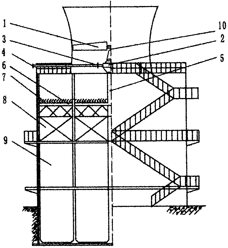
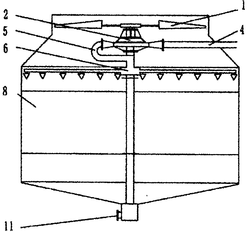
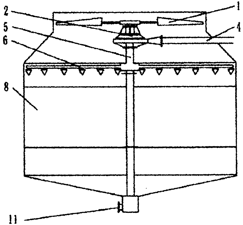
[0029] Figure 1 to Figure 9 It is a representative few of the various forms of the water driven fan cooling tower of the present invention. Figure 1 to Figure 9 1 is the fan blade; 2 is the turbine; 3 is the water inlet; 4 is the water inlet pipe; 5 is the water outlet pipe; 6 is the water distribution pipe; 7 is the water collector; 8 is the filler; 9 is the water spray area; 10 is the drive shaft ; 11 is the water outlet.

[0030] Also refer to Figure 1 to Figure 9 , The water driven fan cooling tower of the present invention will enter the circulating cooling water with proper water head and rated flow through the water inlet pipe 4, and through the water inlet 3 of the water turbine 2, the overflow water turbine 2 is converted into mechanical energy to the drive shaft 10 to drive the wind blades 1 rotates to generate air volume. The air volume is air. The water after the flow turbine 2 flows through the outlet pipe 5 to the water distribution pipe 6, spreads on the surfa...


PUM


Abstract

The invention provides a cooling tower of a hydrodynamic draught fan for cooling circulated cooling water by the air, comprising a tower body, a hydroturbine, a fan blade and a water distributing system, wherein the water inlet of the hydroturbine is communicated to the circulated cooling water through a water inlet pipe, the output shaft of the hydroturbine is rotatably coupled with the fan blade and the water outlet of the hydroturbine is coupled to the water distributing system; the water output region of the water distributing system is located in an air ventilating path in the tower body and the water output direction is opposite to the air ventilating direction in the tower body; and the tower body is constructed as follows: the tower input water head and the flow of the circulated cooling water are coincident to the output power of the hydroturbine and the shaft power of the fan blade. By using the proper water head and the rated water amount of the circulated cooling water as the power, the water flow passes through the efficient hydroturbine and the fan blade is driven by a transmission shaft to generate the air so as to satisfy the cooling effect of the cooling tower.

Description

Technical field [0001] The invention relates to a cooling tower, in particular to a water driven fan cooling tower. Background technique [0002] On March 16, 1954, the U.S. Patent Document U2672328A attempted to use a Pelton turbine in a cooling tower to drive the blades to rotate to obtain cooling efficiency. However, the patent does not follow that the energy required to drive the blades should be consistent with the existing energy inside the circulating water flow. The calculation formula for the power required by the hydraulic turbine to drive the blades to rotate to take wind is W (kW power) = 9.81 × Q (water volume) × H ( Water head)×η (efficiency), the water volume of the cooling tower in the formula is the nominal rated value; the water head is the internal pressure of the circulating cooling water at the point where the tower enters. Due to the need for energy saving, the water head of the existing technology will not have too high affluent . The Pelton turbine is no...

Claims


Application Information

Patent Timeline
Patent Type & Authority Applications(China)
IPC IPC(8): F28C1/00F03B13/00
Inventor 张普妲张飞狂
Owner 张普妲
Why Eureka
Try Eureka