
Wind turbine blade planforms with twisted and tapered tips

a technology of wind turbine blades and planforms, which is applied in the direction of reaction engines, machines/engines, mechanical equipment, etc., can solve the problems of significant reduction in the power produced by blades

Active Publication Date: 2009-12-03
GENERAL ELECTRIC CO
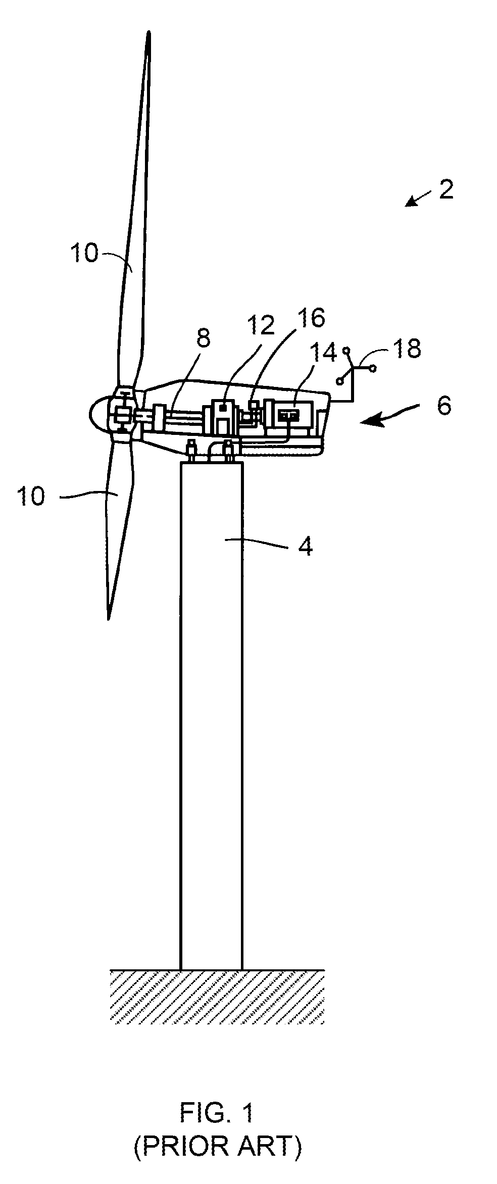
View PDF1 Cites 37 Cited by
  • Summary
  • Abstract
  • Description
  • Claims
  • Application Information

AI Technical Summary

Benefits of technology

[0017]These and other drawbacks associated with such conventional approaches are addressed here in by providing, in various embodiments, a blade for a wind turbine including a total backward twist of between approximately 6 degrees and approximately 15 degrees between an outer approximately 1 percent to approximately 10 percent of a rotor radius of the blade; and an approximate planform distribution within the following ranges

Problems solved by technology

While vortex development can generally be reduced by minimizing the aerodynamic load at the tip of the blade, so-called “tip unloading” typically causes a significant reduction in power that is produced by the blade.

Method used


Image

  • Wind turbine blade planforms with twisted and tapered tips
  • Wind turbine blade planforms with twisted and tapered tips
  • Wind turbine blade planforms with twisted and tapered tips

Examples


Embodiment Construction

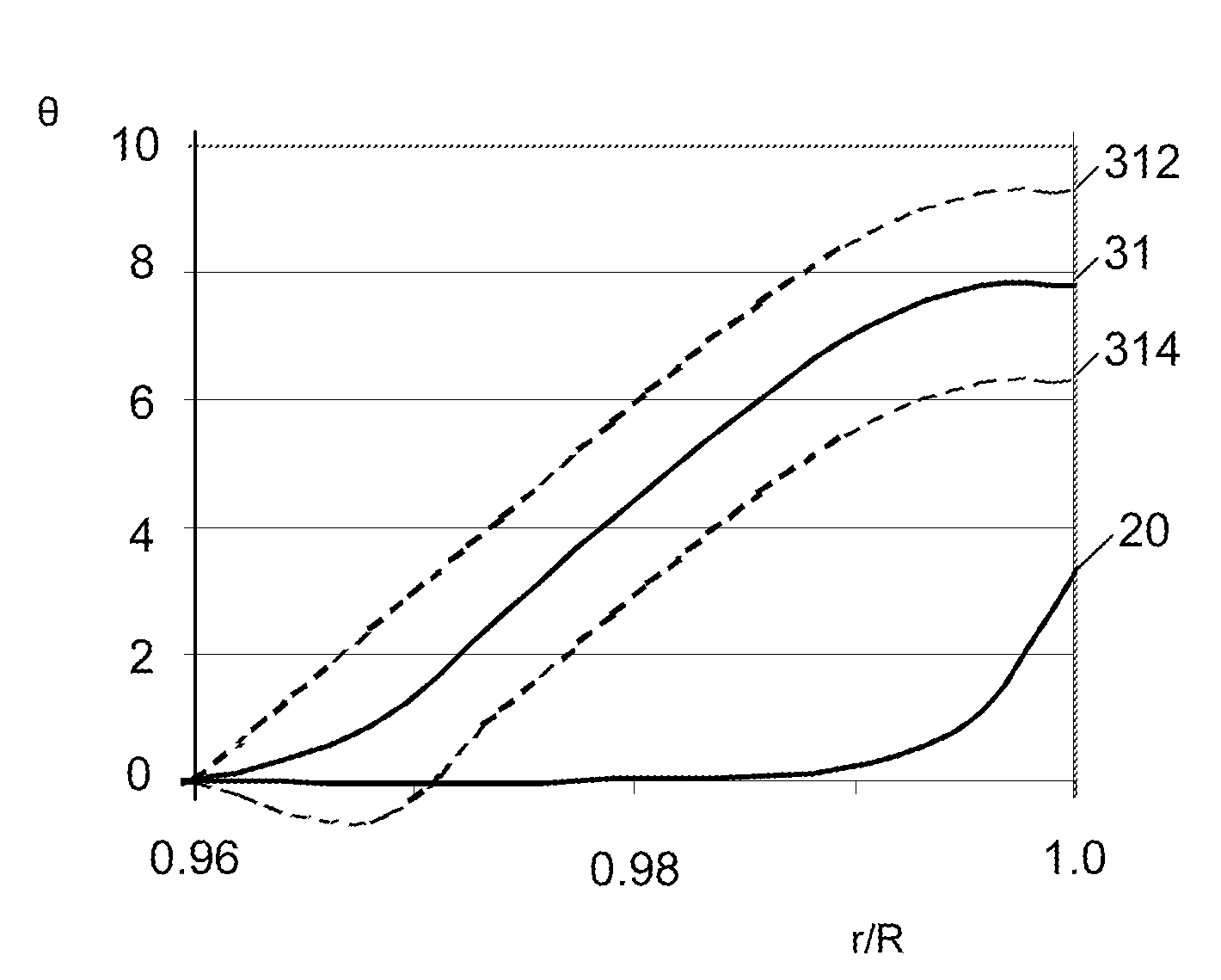
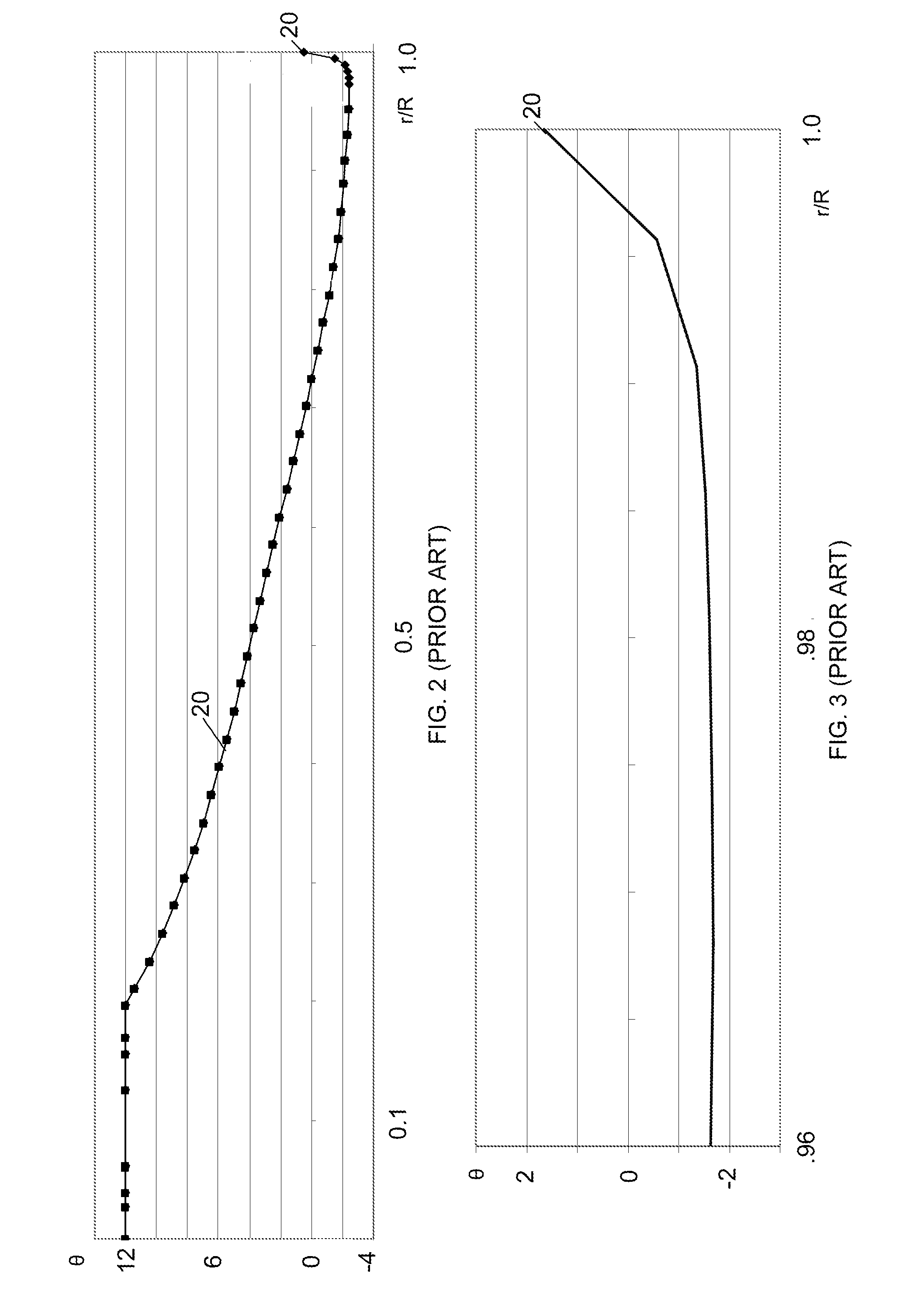
[0030]FIG. 4 is a chart illustrating the conventional blade twist distribution 20 from FIG. 2 along with another blade twist distribution 30. The blade twist distributions 20 and 30 are the same except for in the outer portion of the blade rotor radius near the tip of the blade 10 where the illustrated twist distribution 30 generally corresponds to the following numerical data:

r / Rθ - 300.952128−2.409790.973404−0.289830.9787230.9995730.9840432.2920610.9893623.4212590.9946814.22078814.52427

In comparison to the conventional twist distribution 20, the outer portion of the distribution 30 includes a larger total backward tip twist than the corresponding portion of the conventional twist distribution 20. The tip twist portion of the distribution 30 may also be used with other blades, including blades having other inboard twist distributions. The twist distribution 30 may also be pitched.

[0031]The outer tip twist portion of the twist distribution 30 may also take a variety of other forms. ...


PUM


Abstract

A blade for a wind turbine includes a total backward twist of between approximately 6 degrees and approximately 15 degrees between an outer approximately 1 percent to 10 percent of a rotor radius of the blade; and an approximate planform distribution within the following rangesr / Rc / R(LE)c / R(TE).960.60 to 0.65%−1.42 to −1.34%.9680.54 to 0.59%−1.31 to −1.34%.9740.39 to 0.58%−1.36 to −1.22%.98060.13 to 0.57%−1.45 to −1.06%.9856−0.23 to 0.56%  −1.56 to −0.74%.9906−0.76 to 0.55%  −1.74 to −0.24%.9956−1.44 to 0.54%  −1.99 to 0.23%  1.00−2.17 to 0.54%  −2.27 to 0.44%  where “r / R” is an approximate normalized distance outward from a center of rotation of the blade along a span of the blade; and “c / R(LE)” and “c / R(TE)” are approximate relative positions of a leading (LE) and trailing edge (TE) of a chord “c” expressed as a percentage of a distance outward from the center of rotation at each r / R.

Description

CROSS-REFERENCE TO RELATED APPLICATIONS[0001]The subject matter disclosed here generally relates to that disclosed in U.S. patent application Ser. No. ______ for “Wind Turbine Blades with Twisted Tips” (Attorney Docket No. 230758) and U.S. patent application Ser. No. ______ (Attorney Docket No. 230759) for “Wind Turbine Blades with Twisted and Tapered Tips,” each of which is being filed concurrently with this application and is incorporated by reference here.BACKGROUND OF THE INVENTION[0002]1. Technical Field[0003]The subject matter described here generally relates to fluid reaction surfaces with specific blade structures, and, more particularly, to wind turbines having blade planforms with twisted and tapered tips.[0004]2. Related Art[0005]A wind turbine is a machine for converting the kinetic energy in wind into mechanical energy. If the mechanical energy is used directly by the machinery, such as to pump water or to grind wheat, then the wind turbine may be referred to as a windm...

Claims


Application Information

Patent Timeline
Patent Type & Authority Applications(United States)
IPC IPC(8): F01D5/14F03D11/00
CPCF03D1/0633Y02E10/721F05B2240/301Y02E10/72
Inventor HERR, STEFANKINZIE, KEVIN W.GERBER, BRANDON S.STANDISH, KEVIN J.KOEGLER, KLAUSPETITJEAN, BENOIT P.
Owner GENERAL ELECTRIC CO
Learn More