
Opening/closing member control apparatus and method

Active Publication Date: 2009-12-03
DENSO CORP
View PDF13 Cites 7 Cited by
  • Summary
  • Abstract
  • Description
  • Claims
  • Application Information

AI Technical Summary

Benefits of technology

[0005]The present invention aims for provision of an opening / closing member control apparatus that can stop an opening / closing member before a fully open position without making an impulsive sound while driving the opening / closing member in a direction toward the fully open position, and that can reduce a variation in its stop position, and for the provision of its controlling method.
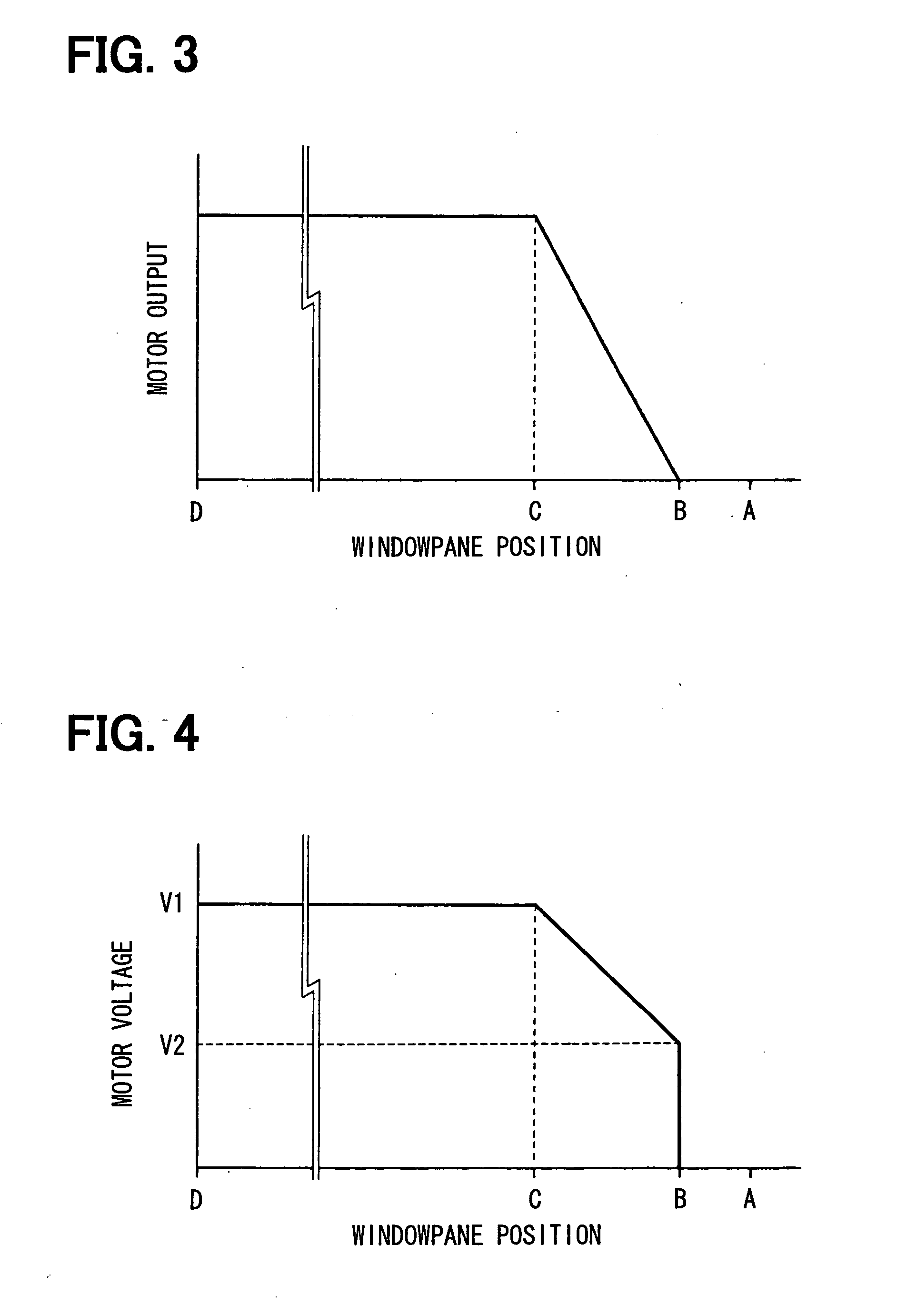
[0006]According to one aspect of the present invention, the opening / closing member control apparatus includes the opening / closing member, a drive mechanism, a position detector, and a control device. The opening / closing member can move between the fully open position and a fully closed position. The drive mechanism drives the opening / closing member to be opened or closed via the drive mechanism by operating a motor. The position detector detects a position of the opening / closing member. The control device controls drive of the motor based on a detected position of the opening / closing member. The control device stores a first set position that is set between the fully open and closed positions, and a second set position that is set between the fully open position and the first set position, as well as adjacently to the fully open position. While driving the opening / closing member in the direction toward the fully open position, the control device reduces a motor output after the opening / closing member reaches the first set position until it reaches the second set position. The control device de-energizes the motor when the opening / closing member reaches the second set position. The second set position is set at a position, from which the opening / closing member cannot reach the fully open position with its movement speed at the time the motor is de-energized.

Problems solved by technology

Thus, when the windowpane is lowered to a bottom lock position, the windowpane is mechanically constrained by a stopper, thereby applying excessive impact force to a drive system.
Accordingly, there is a problem of an occurrence of an offensive impulsive sound, as well as deterioration in durability of the drive system.
However, since such an art still employs a configuration to stop the windowpane at the bottom lock position, an operation stop noise is inevitably made when the windowpane stops.

Method used


Image

  • Opening/closing member control apparatus and method
  • Opening/closing member control apparatus and method
  • Opening/closing member control apparatus and method

Examples


Embodiment Construction

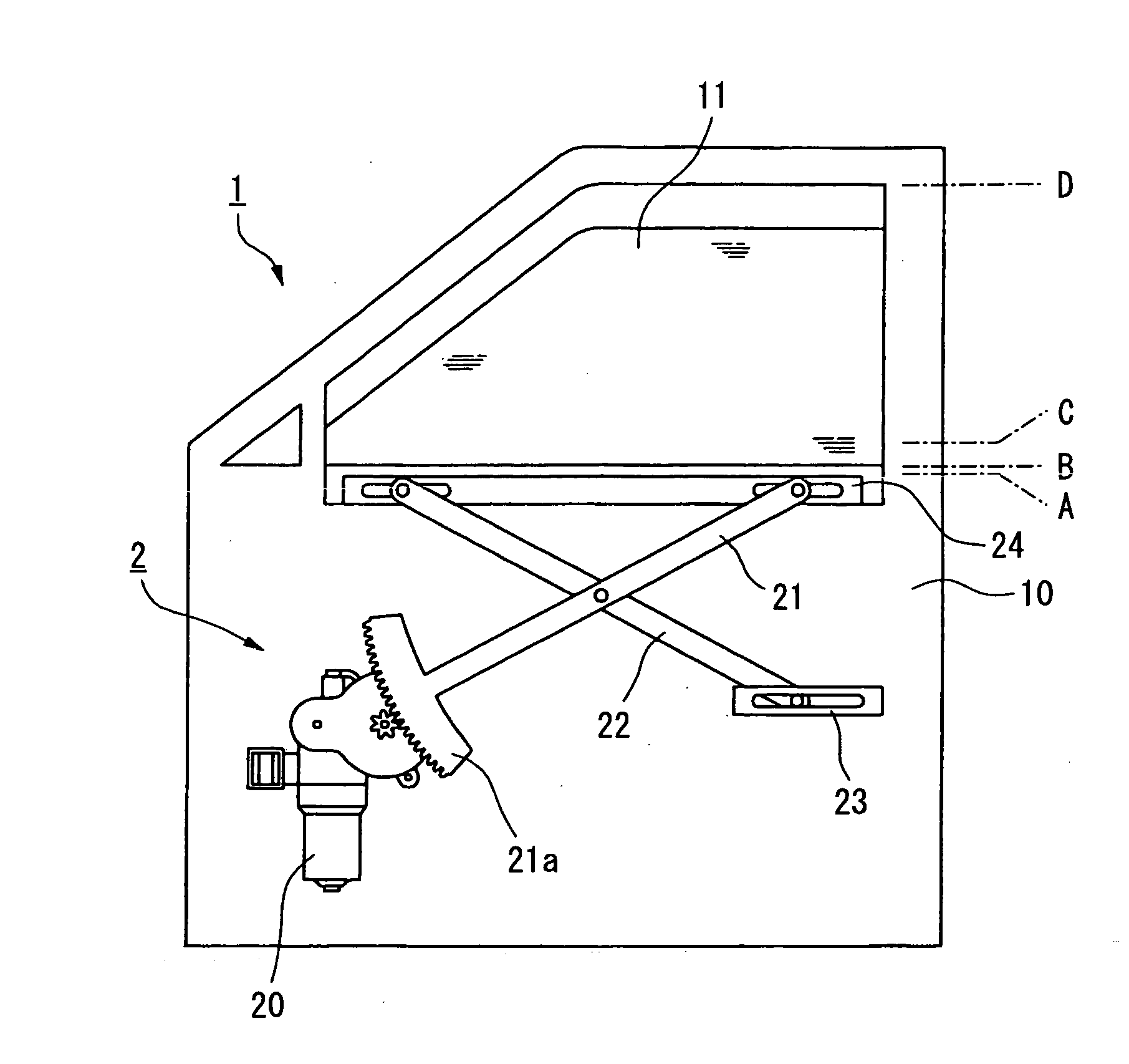
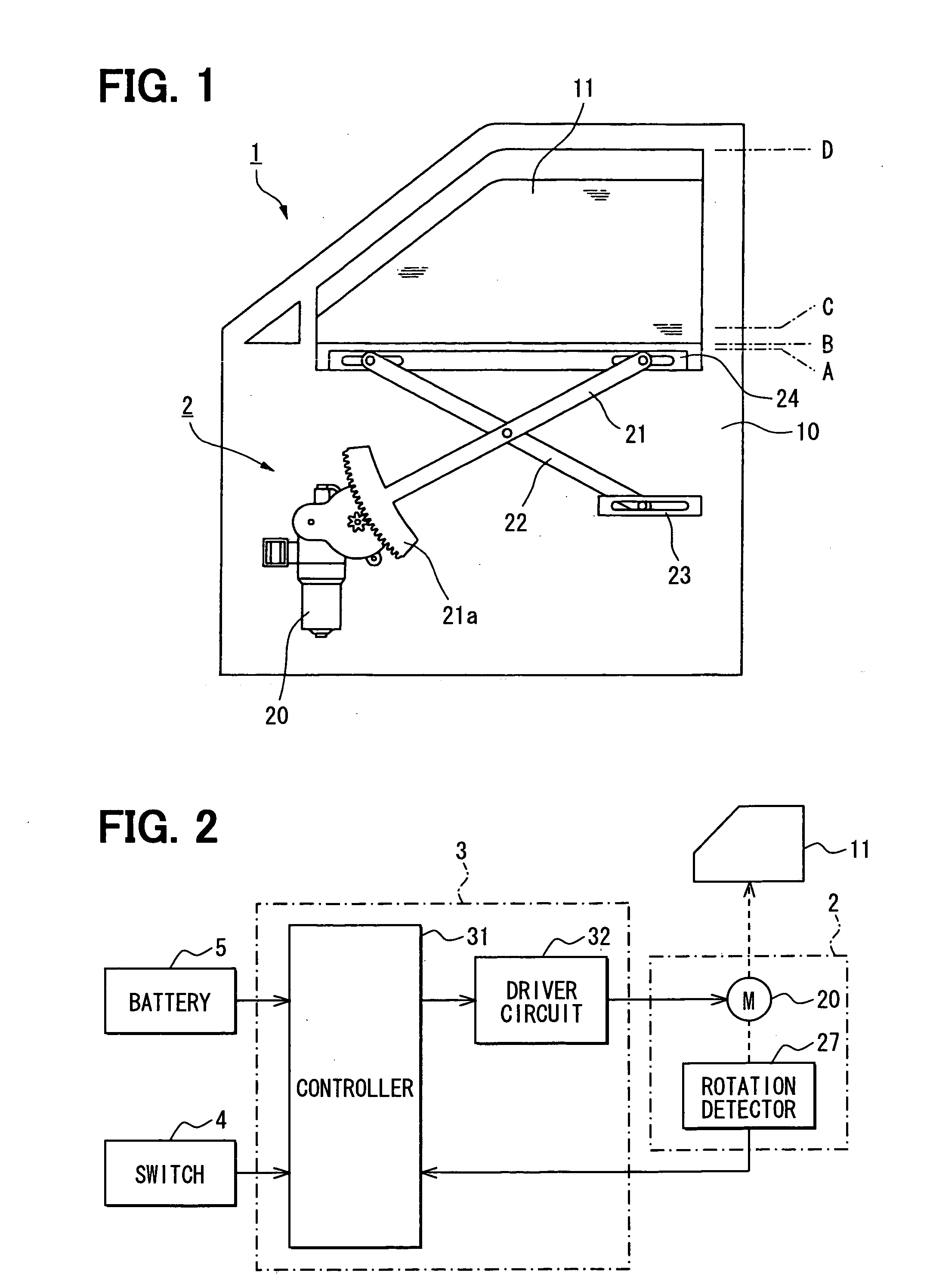
[0017]With reference to FIG. 1, a power window device 1 is provided to move up and down (closes and opens) a windowpane 11 as an opening / closing member arranged in a door 10 of a vehicle by a rotary drive of a motor 20. A drive mechanism 2 that opens and closes the windowpane 11, a control device 3 to control an operation of the drive mechanism 2, and an operating switch 4 for an occupant to command the operation are main components of the device 1.

[0018]The windowpane 11 moves up and down along a rail (not shown) between an upper fully closed position (top) D and a lower fully open position (bottom) A.

[0019]The motor 20 having a speed reducing mechanism secured to the door 10, an elevating arm 21 with a fan-shaped gear 21a driven by the motor 20, a driven arm 22 that is pivoted to cross the elevating arm 21, a fixed channel 23 fixed to the door 10, and a glass-side channel 24 integrated with the windowpane 11 are main components of the drive mechanism 2.

[0020]The motor 20 is config...


PUM


Abstract

A control apparatus for a power window device stores a speed control start position that is set between a fully open position and a fully closed position, and a speed control end position that is set adjacently to the fully open position. While driving a windowpane in a direction toward the fully open position, the control apparatus reduces a motor output after the windowpane reaches the speed control start position until it reaches the speed control end position. The control apparatus de-energizes a motor when the windowpane reaches the speed control end position. The speed control end position is set at a position, from which the windowpane cannot reach the fully open position with its movement speed at the time the motor is de-energized.

Description

CROSS REFERENCE TO RELATED APPLICATION[0001]This application is based on and incorporates herein by reference Japanese Patent Application No. 2005-253102 filed on Sep. 1, 2005.FIELD OF THE INVENTION[0002]The present invention relates to an opening / closing member control apparatus and its controlling method, and, particularly to the opening / closing member control apparatus that controls a speed of an opening / closing member according to an opening / closing position thereof, and to its controlling method.BACKGROUND OF THE INVENTION[0003]Conventionally, a device for raising / lowering a windowpane of a vehicle is constructed, such that the windowpane is raised or lowered through an elevating mechanism by transmitting rotary driving force by an electric motor to the elevating mechanism. In such a raising / lowering device, a driving voltage is simply applied to the electric motor according to rising or descending of the windowpane. Thus, when the windowpane is lowered to a bottom lock positio...

Claims


Application Information

Patent Timeline
IPC IPC(8): G05D3/00
CPCE05F15/695E05Y2900/55
Inventor SAKAI, SHINHIRAI, KAZUYUKISAITO, TOSHIHIRO
Owner DENSO CORP
Learn More