
Composite heat exchanger and composite heat exchanger system

Inactive Publication Date: 2009-12-10
CALSONIC KANSEI CORP
View PDF15 Cites 44 Cited by
  • Summary
  • Abstract
  • Description
  • Claims
  • Application Information

AI Technical Summary

Benefits of technology

[0007]The composite heat exchanger of the first invention includes the air cooled condenser having the pair of tanks and the core part arranged between the tanks thereof; the sub-radiator having the pair of tanks and the core part that is arranged between the tanks thereof and on the same plane as that of the core part of the air cooled condenser, the core part of the sub-radiator being formed with the core part of the air cooled condenser as one unit; and the main radiator having the pair of tanks and the core part that is arranged between the tanks thereof. The one of the tanks of the sub-radiator is formed in the state where the one of the tanks is communicated with the downstream side tank of the main tank. The one of the tanks of the sub-radiator contains the water cooled condenser. The part of the flowing medium that is cooled down by the main radiator is introduced in the sub-radiator to cool flowing medium of the water cooled condenser, and the flowing medium that is cooled by the water cooled condenser is introduced in the air cooled condenser to be cooled. Therefore, the part of the flowing medium can be used as the flowing medium of the sub-radiator, and the main radiator, the sub-radiator, the water cooled condenser and the air cooled condenser, which enables the coolability of mainly the main radiator and the installation thereof on the motor vehicle to be improved.
[0008]In the composite heat exchanger system of the second invention, the part of the flowing medium that is cooled down by the main radiator for cooling the engine is introduced in the sub-radiator for cooling the condenser, and the part of the flowing medium is joined again with the flowing medium of the main radiator. Therefore, the part of the flowing medium can be used as the flowing medium of the sub-radiator, and the number of parts and man hour for piping can be decreased, the composite heat exchanger system can be installed on a motor vehicle.

Problems solved by technology

As a result, there is a problem in that they increase the number of parts thereof and man hours for piping in addition to a lot of trouble of installing them on a motor vehicle.

Method used


Image

  • Composite heat exchanger and composite heat exchanger system
  • Composite heat exchanger and composite heat exchanger system
  • Composite heat exchanger and composite heat exchanger system

Examples


first embodiment

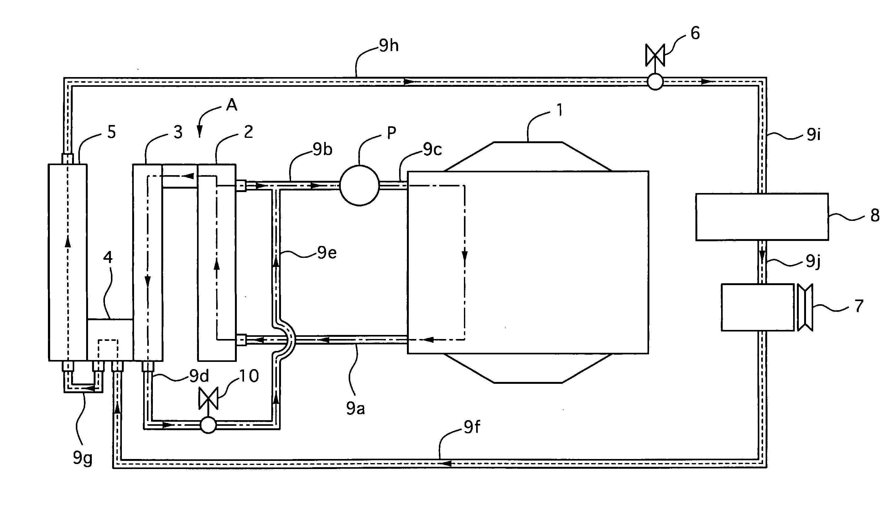
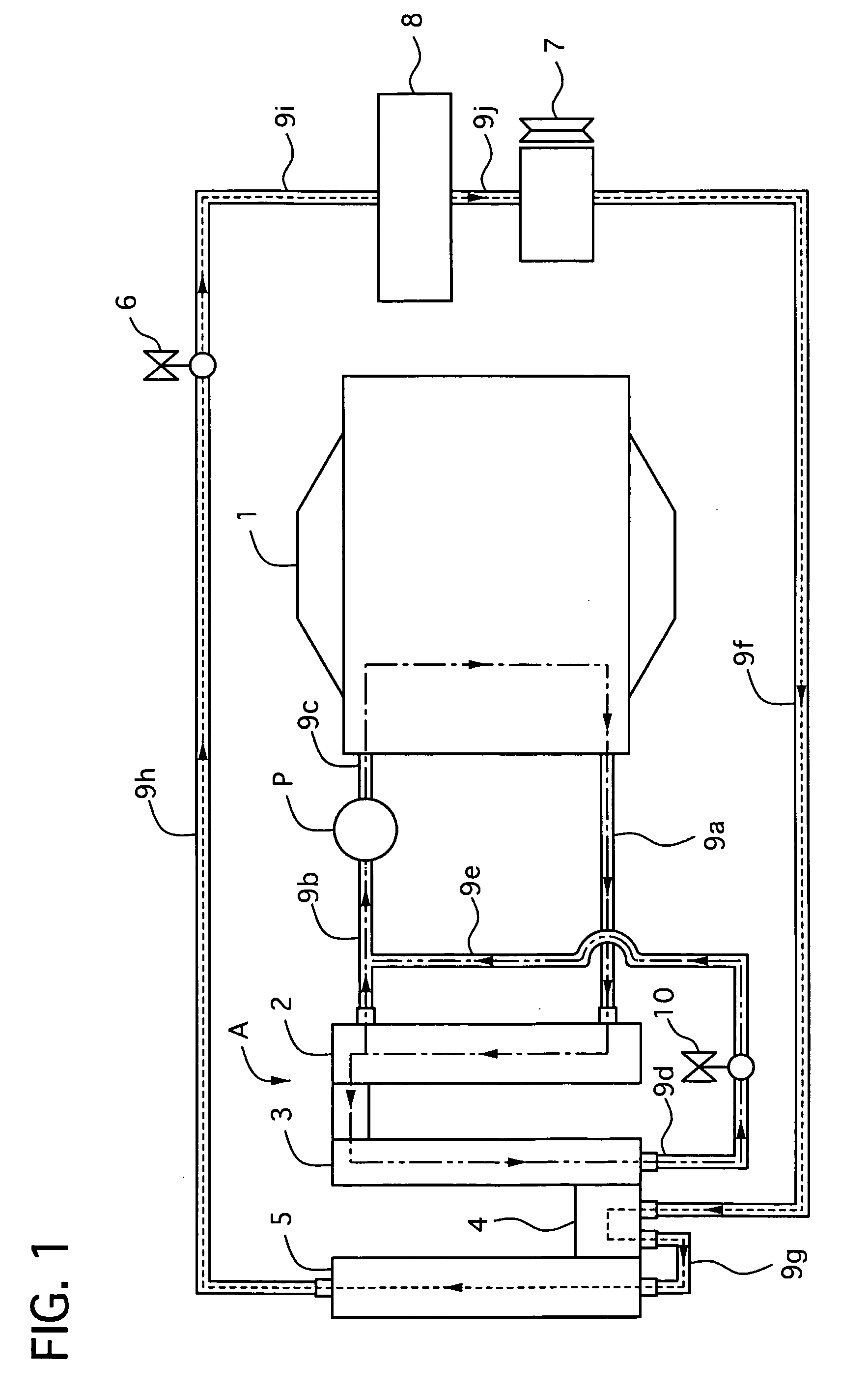
[0070]Hereinafter, a composite heat exchanger and a composite heat exchanger system of a first embodiment will be described.

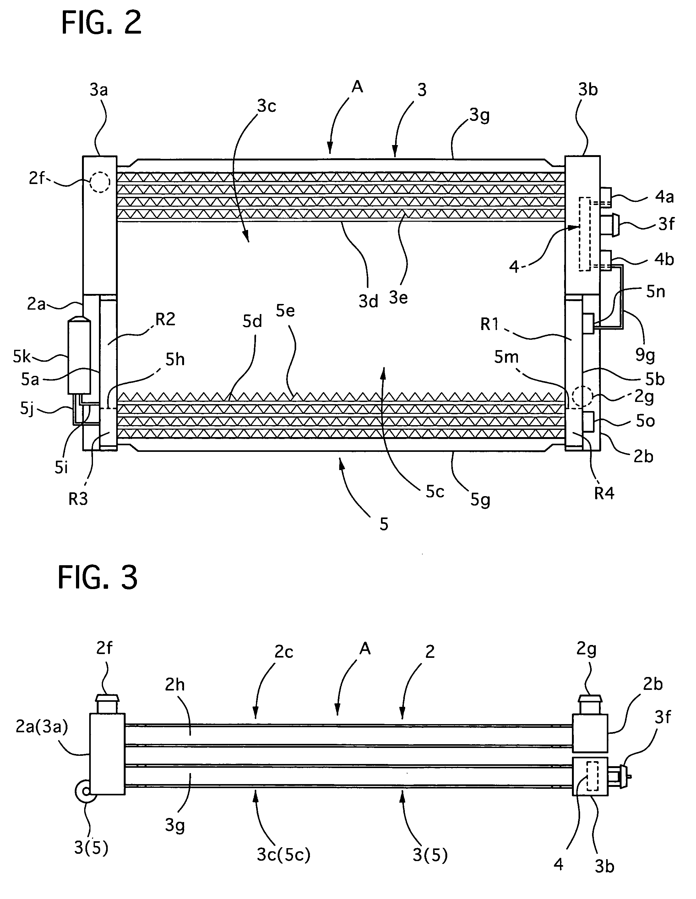
[0071]FIG. 1 is a diagram showing a system configuration of the composite heat exchanger, FIG. 2 is a front view of the composite heat exchanger of the first embodiment 1, FIG. 3 is a plan view of the composite heat exchanger of the first embodiment, FIG. 4 is a diagram illustrating an interior of a tank of a sub-radiator of the first embodiment, and FIG. 5 is a diagram illustrating flow directions of flowing medium of the composite heat exchanger of the first embodiment.

[0072]First, an entire construction of the composite heat exchanger and the composite heat exchanger system of the first embodiment will be described.

[0073]As shown in FIG. 1, a motor vehicle, to which the composite heat exchanger A of the first embodiment is applied, is provided with an engine 1, a main radiator 2, a sub-radiator 3, a water cooled condenser 4, an air cooled condenser 5, an exp...

second embodiment

[0128]Hereinafter, a composite heat exchanger and a composite heat exchanger system of a second embodiment according to the present invention will be described. Incidentally, parts of a construction of the second embodiment similar to those of the first embodiment are indicated by the same reference numbers, and their explanations will be omitted, while only its different parts will be described.

[0129]FIG. 6 is a view illustrating an interior of a tank of a sub-radiator of the second embodiment according to the present invention, FIG. 7 is a front view of a composite heat exchanger of the second embodiment, and FIG. 8 is a diagram illustrating flow directions of flowing medium of the composite heat exchanger of the second embodiment.

[0130]As shown in FIGS. 6 and 7, in the composite heat exchanger B of the second embodiment, an interior of a tank 3a of a sub-radiator 3 is divided to form a fifth chamber R5. The fifth chamber R5 is fluidically communicated with tubes 20a of a lower po...

third embodiment

[0139]Hereinafter, a composite heat exchanger and a composite heat exchanger system of a third embodiment according to the present invention will be described. Incidentally, parts of a construction of the third embodiment similar to those of the second embodiment are indicated by the same reference numbers, and their explanations will be omitted, while only its different parts will be described.

[0140]FIG. 9 is a front view of a composite heat exchanger of the third embodiment according to the present invention.

[0141]As shown in FIG. 9, in the third embodiment, a water cooled condenser 4 is contained in a fifth chamber R5, which has been explained in the second embodiment, and tanks 5a and 5b of an air cooled condenser 5 are arranged bilaterally-symmetrically to those of the second embodiment. These are different from the second embodiment.

[0142]In the thus-constructed composite heat exchanger C, flowing medium of the water cooled condenser 4 is turned once between tanks 3a and 3b of...


PUM


Abstract

A composite heat exchanger system includes an air cooled condenser 5, a sub-radiator 3 and a main radiator 2, and it is formed in a state where a tank 3a of the sub-radiator 3 is communicated with a tank 2a of the main radiator 2. A water cooled condenser 4 is contained in a tank 3b of the sub-radiator 3. A part of flowing medium that is cooled down by the main radiator 2 is introduced in the sub-radiator 3 to cool flowing medium of the water cooled condenser 4. The flowing medium that is cooled down by the water cooled condenser 4 is introduced in the air cooled condenser 5 to be cooled.

Description

TECHNICAL FIELD[0001]The present invention relates to a composite heat exchanger and a composite heat exchanger system which are adapted for a motor vehicle.BACKGROUND OF THE INVENTION[0002]Japanese Patent Application Laid-Open No. 2005-186879, which is invented the inventors of the present invention, discloses a technology of a composite heat exchanger and a composite heat exchanger system where a main radiator for cooling an engine and a sub-radiator for cooling a condenser are arranged.DISCLOSURE OF THE INVENTIONProblem(s) to be Solved by the Invention[0003]However, in the conventional composite heat exchanger and composite heat exchanger system, flowing medium independently flows through the main radiator and the sub-radiator. As a result, there is a problem in that they increase the number of parts thereof and man hours for piping in addition to a lot of trouble of installing them on a motor vehicle.[0004]The present invention is made to solve the above-described problem, and a...

Claims


Application Information

Patent Timeline
IPC IPC(8): F01P3/12F28D1/00F01P3/18B60H1/32
CPCB60H1/00328F01P3/2285F01P7/165F01P2003/187F01P2060/14F28F9/0234F28D1/0435F28D2001/0266F28D2021/0084F28D2021/0085F28D2021/0094F28D1/0417
Inventor IWASAKI, MITSURU
Owner CALSONIC KANSEI CORP
Learn More