Walking robot

a robot and walking technology, applied in the field of walking robots, can solve the problems of generating great inertial force in the leg, complicated control mechanism to effectively attenuate impact, and affecting the operation of the actuator for driving the femoral joint, so as to improve the driving structure, simplify the control mechanism, and reduce the output force

Active Publication Date: 2009-12-10
SAMSUNG ELECTRONICS CO LTD
View PDF8 Cites 33 Cited by
  • Summary
  • Abstract
  • Description
  • Claims
  • Application Information

AI Technical Summary

Benefits of technology

[0012]Accordingly, it is an aspect of the present invention to provide a walking robot capable of simplifying control mechanism by improving a driving structure for a pitch-direction femoral joint and a knee joint and performing natural walking at a relatively lower output force by reducing inertial force generated in legs during walking.
[0028]As described above, according to the walking robot of the embodiment of the present invention, control for the pitch-direction femoral joint and the knee joint can be simplified.
[0029]In addition, the inertial force generated in the legs of the walking robot can be remarkably reduced during walking, so that output force required to drive the legs can be reduced.

Problems solved by technology

However, the joints, in particular, the pitch-direction femoral joint and the knee joint are independently driven by two actuators in the conventional walking robot, so the control mechanism may be complicated to effectively attenuate the impact.
In addition, the actuator for driving the knee joint is positioned adjacent to the knee joint in the conventional walking robot, so great inertial force is generated in the leg during walking and great load is applied to the actuator for driving the femoral joint.

Method used


Image

  • Walking robot
  • Walking robot
  • Walking robot

Examples


Embodiment Construction

[0037]Reference will now be made in detail to the embodiments, examples of which are illustrated in the accompanying drawings, wherein like reference numerals refer to the like elements throughout. The embodiments are described below to explain the present invention by referring to the figures.

[0038]Hereinafter, a walking robot according to exemplary embodiments of the present invention will be described in detail with reference to the accompanying drawings.

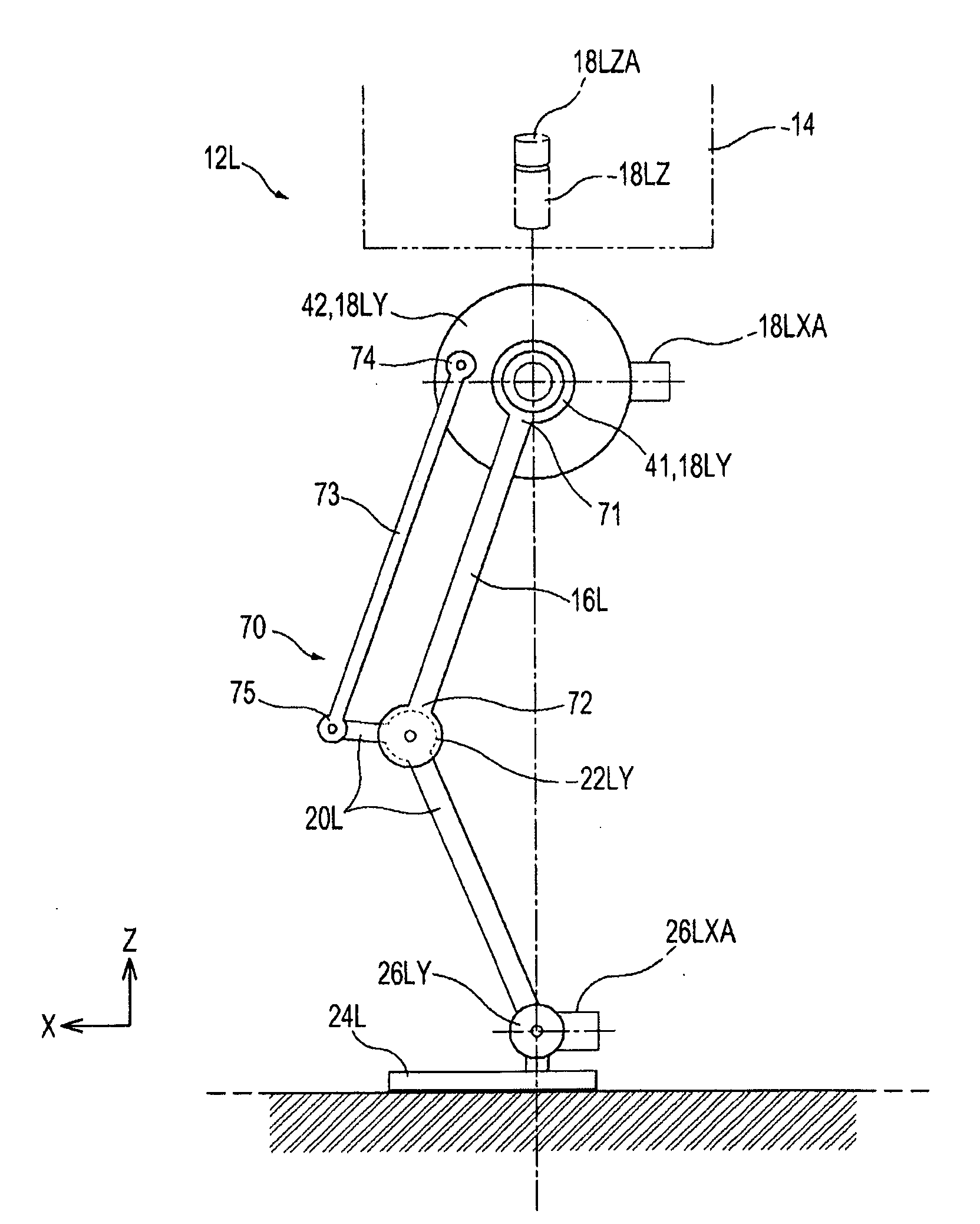
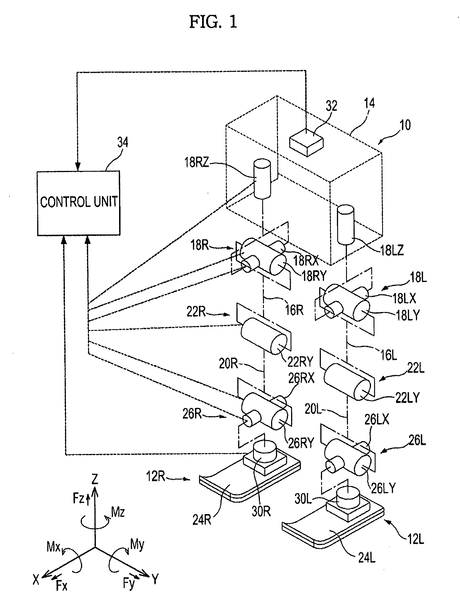
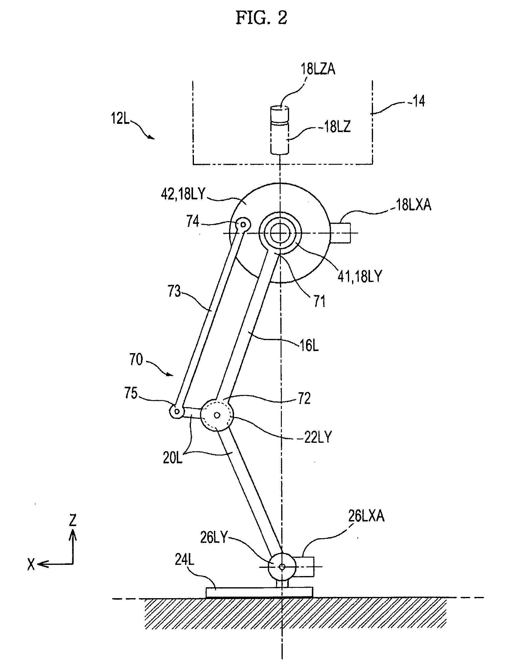
[0039]FIG. 1 is a schematic view showing a joint structure of a leg section of the walking robot according to the embodiment of the present invention.

[0040]As shown in FIG. 1, a biped walking robot 10 (hereinafter, referred to as a robot) includes leg sections 12R and 12L (R denotes right and L denotes left). The leg sections 12R and 12L include femoral joints 18R and 18L, which connect a body 14 to femoral links 16R and 16L, knee joints 22R and 22L, which connect the femoral links 16R and 16L to lower leg links 20R and 20L, and ...


PUM


Abstract

Disclosed is a walking robot having an improved driving structure for a pitch-direction femoral joint and a knee joint. The walking robot includes a pitch-direction actuator driving the pitch-direction femoral joint to rotate a femoral link relative to a body in a pitch direction, and a power transmission unit transferring driving force of the pitch-direction actuator to the knee joint to rotate the lower leg link relative to the femoral link in the pitch direction.

Description

CROSS-REFERENCE TO RELATED APPLICATIONS[0001]This application claims the benefit of Korean Patent Application No. 10-2008-0052913 filed on Jun. 5, 2008, in the Korean Intellectual Property Office, the disclosure of which is incorporated herein by reference.BACKGROUND[0002]1. Field[0003]The present invention relates to a walking robot. More particularly, the present invention relates to a walking robot having an improved driving structure for a pitch-direction femoral joint and a knee joint.[0004]2. Description of the Related Art[0005]Various types of walking robots, such as a biped walking robot or a four-legged walking robot, have been developed for the purpose of household use, military use, or industrial use.[0006]Korean Unexamined Patent Publication No. 2001-50273 discloses a humanoid in the form of a biped walking robot.[0007]The robot disclosed in Korean Unexamined Patent Publication No. 2001-50273 includes a body, a head provided at an upper end portion of the body, a pair of...

Claims


Application Information

Patent Timeline
Patent Type & Authority Applications(United States)
IPC IPC(8): B62D57/032
CPCB62D57/032B25J9/162B25J17/0258Y10S901/01Y10S901/16
Inventor YANG, SOO SANGOH, YEON TAEKLEE, YOUN BAEK
Owner SAMSUNG ELECTRONICS CO LTD
Why Eureka
Try Eureka