
Hemodialysis apparatus

Inactive Publication Date: 2007-07-10
JMS CO LTD
View PDF7 Cites 9 Cited by
  • Summary
  • Abstract
  • Description
  • Claims
  • Application Information

AI Technical Summary

Benefits of technology

[0005]The object of the present invention is to provide a hemodialysis apparatus that can achieve the following effects:
[0006](1) The control mechanism is simple, and there is little risk of misoperation or out-of-control.
[0007](2) As there is no need of difficult installation or unnecessary operation, the operator can easily operate without difficulty.

Problems solved by technology

A rapid or excessive water removal will decrease excessively patient's blood circulating volume, and it may cause reduction of blood pressure, shock or the like.
On the contrary, if the water removal is slow, it will take a long time for blood purification, and if sufficient water removal cannot be made, there is a fear that hypertension, heart failure or the like can occur.
Concerning this apparatus, it is convenient as the water removal is controlled directly according to the measured body fluid condition, but on the other hand, as the water removal is controlled directly by the measured value, in case the result of the measuring means is not accurate or a trouble happens, it may cause a significant problem.
However, the apparatus becomes complicated when an independent line or safety mechanism is disposed and the operation becomes difficult.
Furthermore, the cost of the apparatus will rise.
However, this apparatus only recognizes if the water removal control is performed under the same control condition at the time of the initiation of dialysis, by comparing with the blood concentration measured before the initiation of dialysis, and it is not possible to perform adequate water removal to each patent.
Furthermore, if the water removal is not performed according to the condition, the operator has to adjust each time the water removal volume or fluid replacement volume.
Thus, even though it was safe, it was complicated and the human cost was high.
Moreover, as for said apparatus, a means for measuring the blood condition is disposed on the line at the vein fluid side of the blood cycle, the blood condition after having passed the blood treatment machine (dialyser) is measured, thus it may not reflect the patient's direct blood condition.
As for the hemodialysis apparatus mentioned above, it was possible to manage surely the blood indication level at each point during hemodialysis treatment, but because it was necessary to define the region of the target blood indication level at each point, the operation was complicated.
Furthermore, as the defined blood indication level was designated as a range, as long as a blood indication level exists within the defined range, even it is at the absolute edge of the range, the control mechanism of the hemodialysis apparatus would not work.
Therefore, in case the blood indication level actually measured is slightly missing the point from the target, there was a fear that the control would be delayed.
Furthermore, as for said apparatus, minute details were defined in each region, and the control is carried out according to these, the physiological water removal adequate to each patient was difficult to be carried out.
On the contrary, when the water removal mild to the living body is intended to be carried out, it happened that the water removal volume which was determined beforehand, can not be attained.

Method used


Image

  • Hemodialysis apparatus
  • Hemodialysis apparatus
  • Hemodialysis apparatus

Examples


example 1

1. EXAMPLE 1

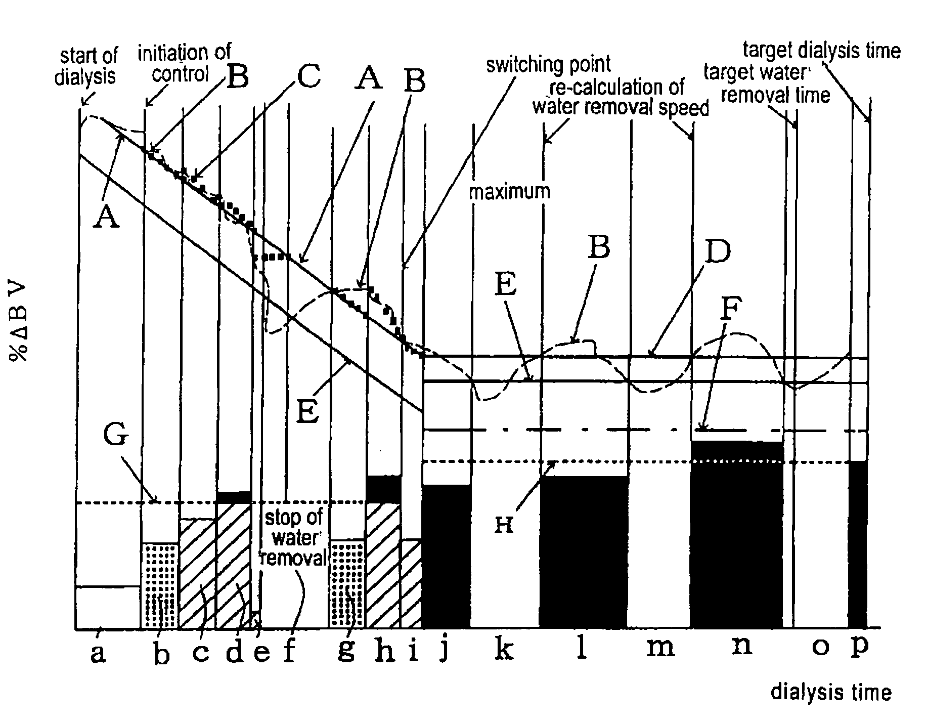
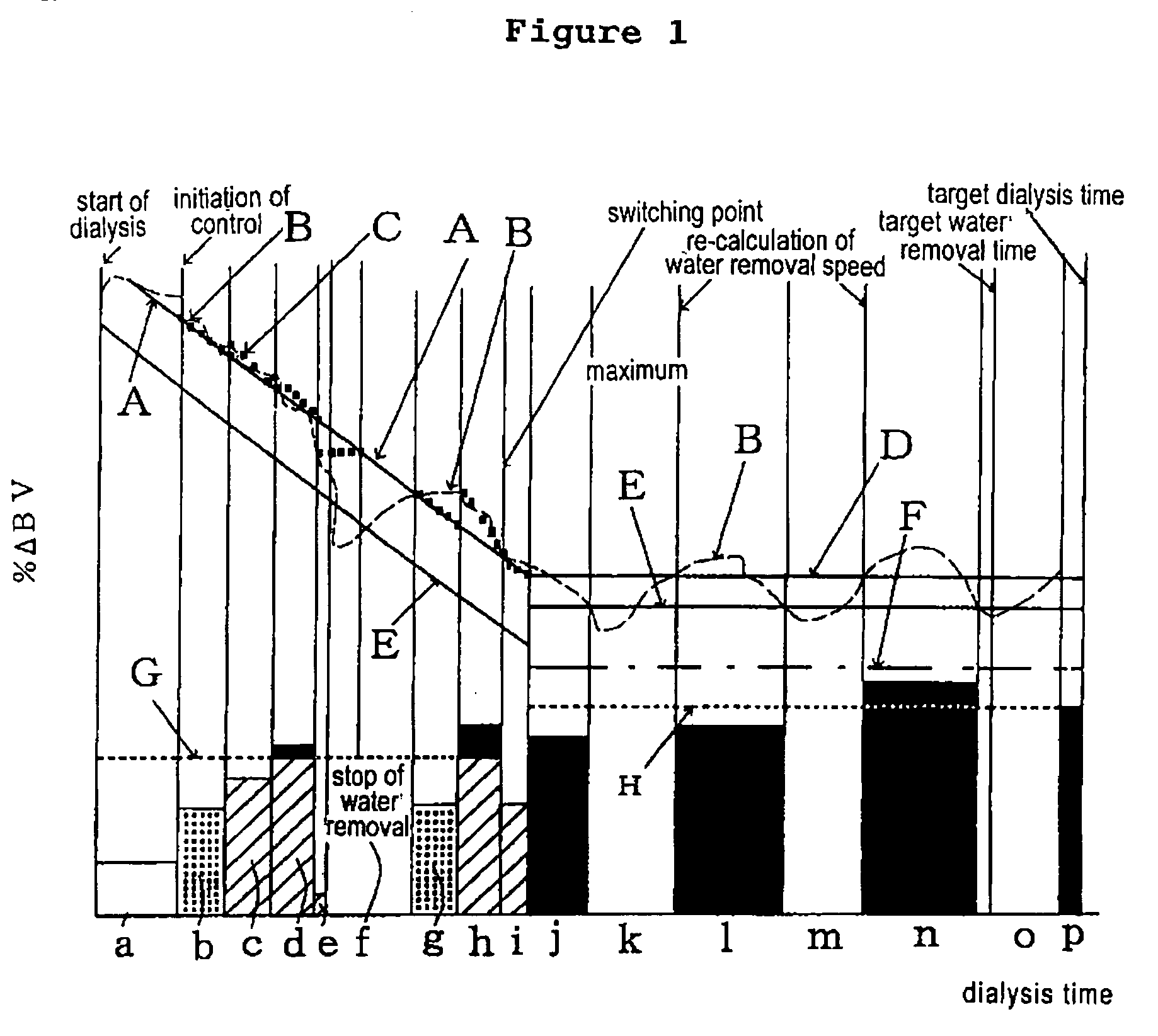
[0079]The embodiments of control for hemodialysis operation of the hemodialysis apparatus of the present invention is explained according to FIG. 1. In the bottom half of FIG. 1, the defined water removal speed is shown.

[0080]As it is shown in FIG. 1, the maximum water removal speed line G and H are defined in the former and latter part of the dialysis operation, in the bottom half of FIG. 1, the defined water removal speed (or the history) in the former and latter part of the dialysis operation are shown.

Former Part of the Dialysis Operation

(1) Start of Dialysis

[0081]When starting dialysis, as the BV level is unstable, the water removal is not performed at the time of the initiation of dialysis (water removal speed is 0), only circulation outside the body is performed, and it is waited for the time interval to pass until the BV level stabilizes (period a). During the period a, the patient's primary blood level (BV0) could be calculated according to the above (I).

[0082](...


PUM

PropertyMeasurementUnit
Volumeaaaaaaaaaa
Blood volumeaaaaaaaaaa

Abstract

A hemodialysis apparatus includes means for measuring or calculating a blood volume or a blood volume change as a blood index level, a hemodialysis means, and a controlling means that controls hemodialysis conditions of the hemodialysis means according to the blood index level. The controlling means controls the hemodialysis means so that hemodialysis operation is carried out without performing water removal at the time of the initiation of the hemodialysis operation until the blood volume stabilizes. The hemodialysis operation is carried out by performing water removal after the blood volume is stabilized by the hemodialysis operation without performing water removal, and that is a constitution so that it is possible to calculate the primary blood volume (BV0) of each patient according to the following formula (I), from % ΔBV of hemodialysis operation which has been carried out before the blood volume is stabilized, and the increased blood volume circulating outside the body. The primary blood volume (BV0)=increased blood volume circulating outside the body (space outside the body) / % ΔBVx. (I), wherein % ΔBVx is the ratio of the volume change of the blood volume (BV) when hemodialysis is performed without performing water removal.

Description

TECHNICAL FIELD[0001]The present invention relates to a blood treatment apparatus, especially to a hemodialysis apparatus which can control water removal conditions and water removal speed so as to prevent excessive water removal and also lack of water removal in the contrary, which occur frequently during hemodialysis.BACKGROUND ART[0002]For treating patients with impaired kidney function, treatments by purifying blood by dialysis or filtration via semipermeable membrane have been provided conventionally. As for this apparatus, it is important to appropriately maintain the blood volume circulating in the patient body, to perform safe and effective blood purification. A rapid or excessive water removal will decrease excessively patient's blood circulating volume, and it may cause reduction of blood pressure, shock or the like. On the contrary, if the water removal is slow, it will take a long time for blood purification, and if sufficient water removal cannot be made, there is a fea...

Claims


Application Information

Patent Timeline
IPC IPC(8): B01D61/32A61M1/14A61M1/36
CPCA61M1/14A61M1/1613A61M1/3607A61M1/36A61M2205/3379
Inventor IKEDA, ATSUSHI
Owner JMS CO LTD
Learn More