Liquid crystal electric control zero crossing scanning leaky-wave antenna based on half-mode pectinate line waveguide

A leaky-wave antenna and comb-line technology, which is applied in the field of microwave antenna engineering, can solve problems such as difficult zero-crossing scanning and electronically controlled scanning leaky-wave antennas are difficult to work, and achieve the effects of large power capacity, low loss, and improved radiation efficiency

Active Publication Date: 2015-10-28
北京超材信息科技有限公司
View PDF5 Cites 10 Cited by
  • Summary
  • Abstract
  • Description
  • Claims
  • Application Information

AI Technical Summary

Problems solved by technology

[0006] The purpose of the present invention is to solve the problem that the traditional electronically controlled scanning leaky wave antenna based on traditional electric adjustment elements such as varactor diodes is difficult to work in the microwave high frequency band and that the existing liquid crystal electronically controlled fixed frequency scanning leaky wave antenna is not easy to realize zero-crossing scanning and To solve the problem of specially designed bias circuit, a liquid crystal electronically controlled zero-crossing scanning leaky wave antenna based on half-mode comb line waveguide is provided

Method used


Image

  • Liquid crystal electric control zero crossing scanning leaky-wave antenna based on half-mode pectinate line waveguide
  • Liquid crystal electric control zero crossing scanning leaky-wave antenna based on half-mode pectinate line waveguide
  • Liquid crystal electric control zero crossing scanning leaky-wave antenna based on half-mode pectinate line waveguide

Examples


specific Embodiment approach 1

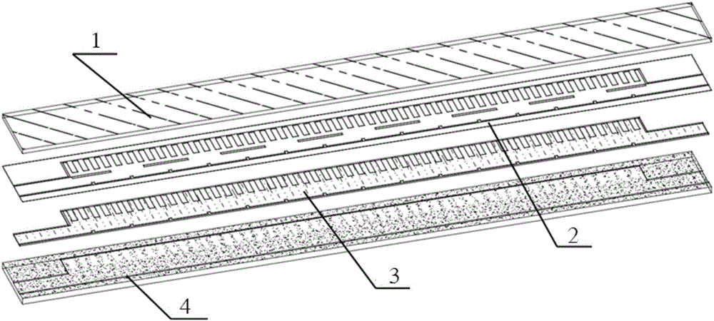
[0029] Specific implementation mode one: the following combination Figure 2 to Figure 5 Describe this embodiment mode. The liquid crystal electronically controlled zero-crossing scanning leaky wave antenna based on the half-mode comb line waveguide described in this embodiment mode includes a top dielectric plate layer 1, a metal layer 2, a liquid crystal layer 3 and a bottom waveguide groove 4;

[0030] A metal layer 2 is arranged between the top dielectric plate layer 1 and the bottom waveguide groove 4, and the bottom waveguide groove 4 is a rectangular plate with a longitudinal groove structure on the upper surface, and a liquid crystal layer 3 is arranged in the longitudinal groove;

[0031] The top dielectric plate layer 1 and the metal layer 2 are tightly integrated into one body through mechanical processing, electroplating, hot pressing or microelectronic technology;

[0032] The bottom waveguide groove 4 is a rectangular plate with a vertical groove structure on the...

specific Embodiment approach 2

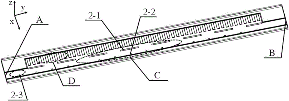
[0040] The external dimensions of the bottom waveguide groove 4 are not limited, and the longitudinal grooves on the bottom waveguide groove 4 are made by mechanical processing, microelectronics technology or electroplating technology. m ×a LC × d LC Tank body, take the slot width a LC >λ / 2, λ is the working wavelength, groove depth d LC image 3 in the z direction. Above the liquid crystal is a metal layer. Since the width of the comb line structure is smaller than that of the waveguide groove, the metal layer and the waveguide groove are electrically isolated. Therefore, the connection between the metal layer and the waveguide does not require direct connection and sealing with insulating glue. Specific implementation mode two: the following combination Figure 6 to Figure 12 This implementation mode is described, and the antenna structure of the first implementation mode is further described in this implementation mode in combination with specific examples.

[0041] As...


PUM


Abstract

The invention provides a liquid crystal electric control zero crossing scanning leaky-wave antenna based on half-mode pectinate line waveguide, belongs to the technical field of microwave antenna engineering, and solves problems that an electric control scanning leaky-wave antenna of conventional electrically controlled elements is difficult to work at a microwave high-frequency band. The liquid crystal electric control zero crossing scanning leaky-wave antenna comprises a top part dielectric plate layer, a metal layer, a liquid crystal layer and a bottom part waveguide slot. The metal layer is arranged between the top part dielectric plate layer and the bottom part waveguide slot. The bottom part waveguide slot has a longitudinal slot structure arranged at the upper surface of a rectangular plate. The liquid crystal layer is arranged in the longitudinal slot. The metal layer has a half-mode pectinate line waveguide structure. N periodic seam units are arranged between the column of pectinate teeth and the longitudinal edge of the opposite side of a rectangular waveguide frame in a rectangular waveguide frame area. The N periodic seam units include a group s longitudinal seam columns and a group of transverse seam columns. The transverse seam columns are arranged between the longitudinal seam columns and the pectinate teeth. Equivalent series inductance of electromagnetic wave is enabled to be increased by the periodic transverse seams and equivalent parallel induction is enabled to be increased by the periodic longitudinal seams when electromagnetic wave is transmitted between the bottom part waveguide slot and the metal layer.

Description

technical field [0001] The invention belongs to the technical field of microwave antenna engineering. It can be widely used in modern wireless mobile communication, satellite communication in motion and various radar systems. Background technique [0002] Since the leaky wave antenna was proposed by W.W.Hansen in the 1940s, its unique radiation characteristics and excellent lobe scanning characteristics have made the leaky wave antenna a hot spot in the field of antenna research. The original leaky wave antenna is composed of a slotted rectangular waveguide, and its essence is that when the electromagnetic wave propagating on the waveguide structure is a fast wave, it will radiate part of the electromagnetic wave to the space. In recent decades, research on leaky-wave antennas has developed rapidly, especially planar leaky-wave antennas have been widely studied, because planar leaky-wave antennas can be directly processed on printed circuit boards (PCBs), with low profile, ...

Claims


Application Information

Patent Timeline
Patent Type & Authority Applications(China)
IPC IPC(8): H01Q1/22H01Q1/38H01Q23/00H01Q3/22
Inventor 孟繁义
Owner 北京超材信息科技有限公司
Why Eureka
Try Eureka