
Remote operation of a motor control center subunit disconnect

a technology of motor control center and subunit, which is applied in the direction of circuit breaker switches, switch power arrangements, contact mechanisms, etc., can solve the problems of shortening the life of circuit breakers, high undesirable need for operators to be in proximity to the motor control center to manually actuate the unit disconnect, and time-consuming putting on and removing protective gear

Active Publication Date: 2009-12-10
EATON INTELLIGENT POWER LIMITED
View PDF89 Cites 31 Cited by
  • Summary
  • Abstract
  • Description
  • Claims
  • Application Information

AI Technical Summary

Benefits of technology

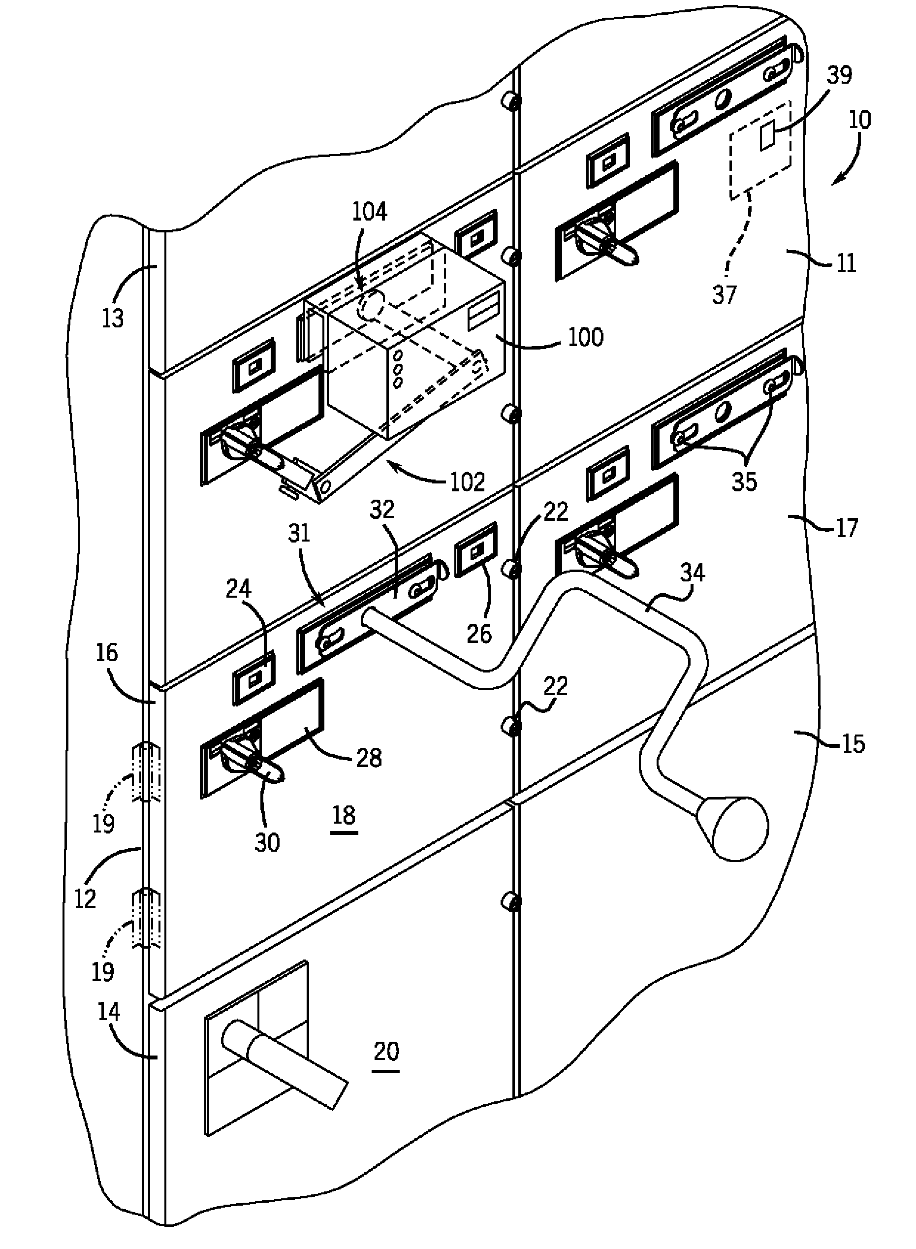
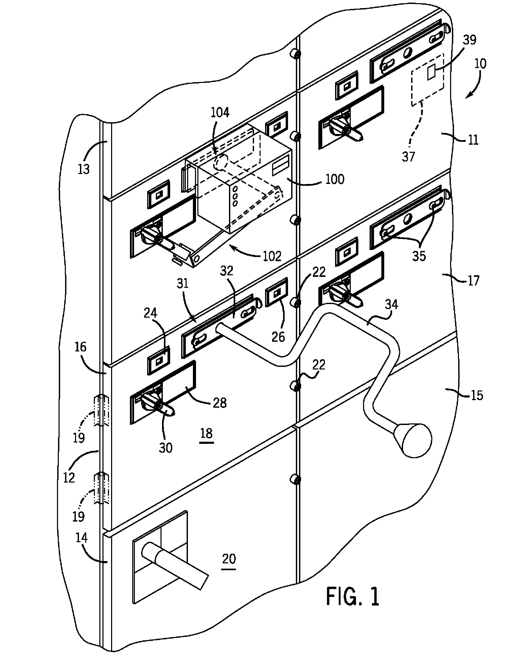
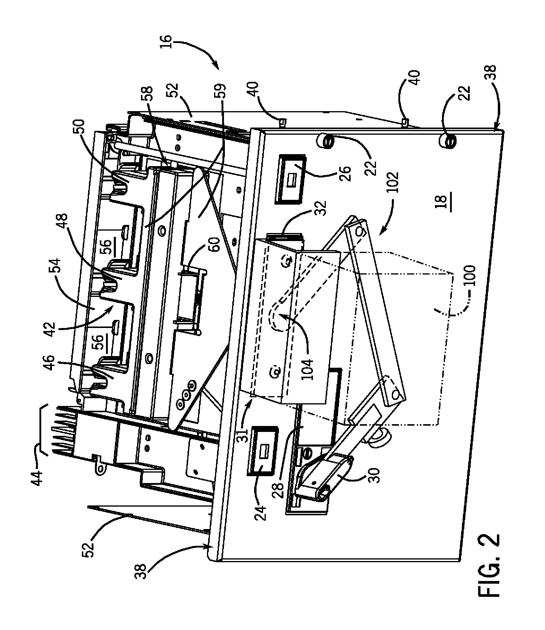
[0007]The present invention provides a system and method for electrically connecting and disconnecting motor control components of the motor control center subunit to a power supply from a remote location. In one embodiment, the system and method described herein provides for the connection and/or disconnection of supply power to the motor control components via the control of a subunit circuit breaker from a remote location.
[0008]Therefore, in accordance with one aspect of the present invention, a motor control center subunit includes a subunit housing configured to fit within a motor control center and a subunit disconnect configured to selectively control a supply power to motor control components of the subunit housing. The motor control center subunit also includes a control mechanism attached to the subunit housing to activate and deactivate the subunit disconnect

Problems solved by technology

In “feeder” motor control center units, however, such actuation of the unit disconnect acts to energize the motor circuit.
The putting-on and removal of such protective gear can be time consuming and the need for the operator to be in proximity to the motor control center to manually actuate the unit disconnect is highly undesirable.
While the use of a shunt trip is possible for remotely actuating (i.e., opening) the circuit breaker / unit disconnect, the use of shunt trips shortens the life of the circuit breaker.
That is, while shunt tripping may be a practical means for opening the circuit breaker remotely, use of a shunt trip results in the need for the breaker to be cycled through a reset action.
Additionally, use of the shunt trip to repeatedly open the circuit breaker increases wear on the circuit breaker, as such mechanisms are typically designed for only 10% shunt trip operation.

Method used


Image

  • Remote operation of a motor control center subunit disconnect
  • Remote operation of a motor control center subunit disconnect
  • Remote operation of a motor control center subunit disconnect

Examples


Embodiment Construction

[0020]The following description makes reference to supply power, supply power lines, motor power, load power, line power, and the like. It is appreciated that such terms may refer to a variety of both common and uniquely conditioned voltage and current characteristics, including but not limited to, three phase AC power, single phase AC power, DC power, multiple DC power lines, or any combination thereof. Such power characteristics will be generally referred to as being provided on a bus, supply line, or riser of a motor control center. However, it is appreciated that the present invention may find applicability in other power connectivity configurations adapted or apart from motor control centers, such as high power electrical switchboard arrangements and panel board arrangements. An example of supply power commonly used in motor control centers is 480V three-phase AC power distributed over three separate supply bus bars.

[0021]References to “motor control components” shall be unders...


PUM


Abstract

A system and method are provided for remotely actuating a subunit disconnect in a motor control center subunit. A motor control center subunit includes a subunit housing configured to fit within a motor control center and a subunit disconnect configured to selectively control a supply power to motor control components of the subunit housing. A control mechanism is attached to the subunit housing to activate and deactivate the subunit disconnect and a remote control device communicates with the control mechanism and is configured to operate the control mechanism to activate and deactivate the subunit disconnect.

Description

BACKGROUND OF THE INVENTION[0001]The present invention relates generally to motor control systems, and more particularly, to motor control center subunits having a remote disconnect system which governs the connection of motor control components to supply power. In one embodiment, the system and method described herein provides for the connection and / or disconnection of supply power to the motor control components via the control of a subunit circuit breaker from a remote location.[0002]A motor control center is a multi-compartment steel enclosure with a bus system to distribute electrical power, on a common bus system, to a plurality of individual motor control units mountable within the compartments. The individual motor control center subunits are commonly referred to as “buckets” and are typically constructed to be removable, pull-out units that have, or are installed behind, individual sealed doors on the motor control center enclosure. These buckets may contain various motor c...

Claims


Application Information

Patent Timeline
IPC IPC(8): H01H3/20H01H3/26H01H3/04
CPCH01H3/26H01H3/264H02B1/36H02B11/12H01H3/58H02B11/24
Inventor MORRIS, ROBERT A.YEE, EDGARBRYLL, JARED A.LEEMAN, DANIEL J.KROUSHL, DANIEL B.
Owner EATON INTELLIGENT POWER LIMITED
Learn More