
Spot Welding Method and Spot Welding System

a welding electrode and spot welding technology, applied in welding equipment, metal-working equipment, manufacturing tools, etc., can solve the problems of affecting the clamping-pressing force, the actual pressure produced may not reach the specified value, and the electrodes melt and deform, so as to achieve accurate control of the pressing force of welding electrodes

Inactive Publication Date: 2009-12-10
NACHI-FUJIKOSHI
View PDF5 Cites 8 Cited by
  • Summary
  • Abstract
  • Description
  • Claims
  • Application Information

AI Technical Summary

Benefits of technology

The present invention provides a spot welding method that accurately controls the pressing force of welding electrodes driven by a servomotor. This is achieved by measuring the pressing force actually applied when pressing the work and regulating the driving current to the servomotor based on the measured value. A spot welding system according to the invention includes welding electrodes, a servomotor, and a control unit for controlling operation of the servomotor. The control unit has a pressing force control circuit that receives a measured value of the pressing force and regulates the driving current to the servomotor to control the pressing force applied to the work. This ensures excellent welding quality and attains improvement of operating efficiency. The invention also provides a feedback control method for controlling the clamping-pressing force, which allows for control of the force with no steady deviation and with excellent response characteristics. The output of the pressing force control circuit is monitored to detect any failure in the electric pressing gun.

Problems solved by technology

However, even when the servomotor is driven based on the above correlation function, the pressing force actually produced may not reach the specified value.
Also, the electrodes melt and deform during welding, and a secular change of electrical and mechanical loss of the servomotor and electric welding gun also affects the clamping-pressing force.
For example, in the above described method of updating the correlation function at every given time period, it is not known whether or not the specified pressing force is attained at the actual welding position, and the clamping-pressing force cannot be accurately controlled.
Also, in the method of regulating the pressing force based on the position of the driving servomotor, the generation state of the pressing force varies significantly depending on the material of a work clamped and on the state of the electric welding gun and welding electrodes, and it is extremely difficult to stabilize the pressing force.

Method used


Image

  • Spot Welding Method and Spot Welding System
  • Spot Welding Method and Spot Welding System
  • Spot Welding Method and Spot Welding System

Examples


first embodiment

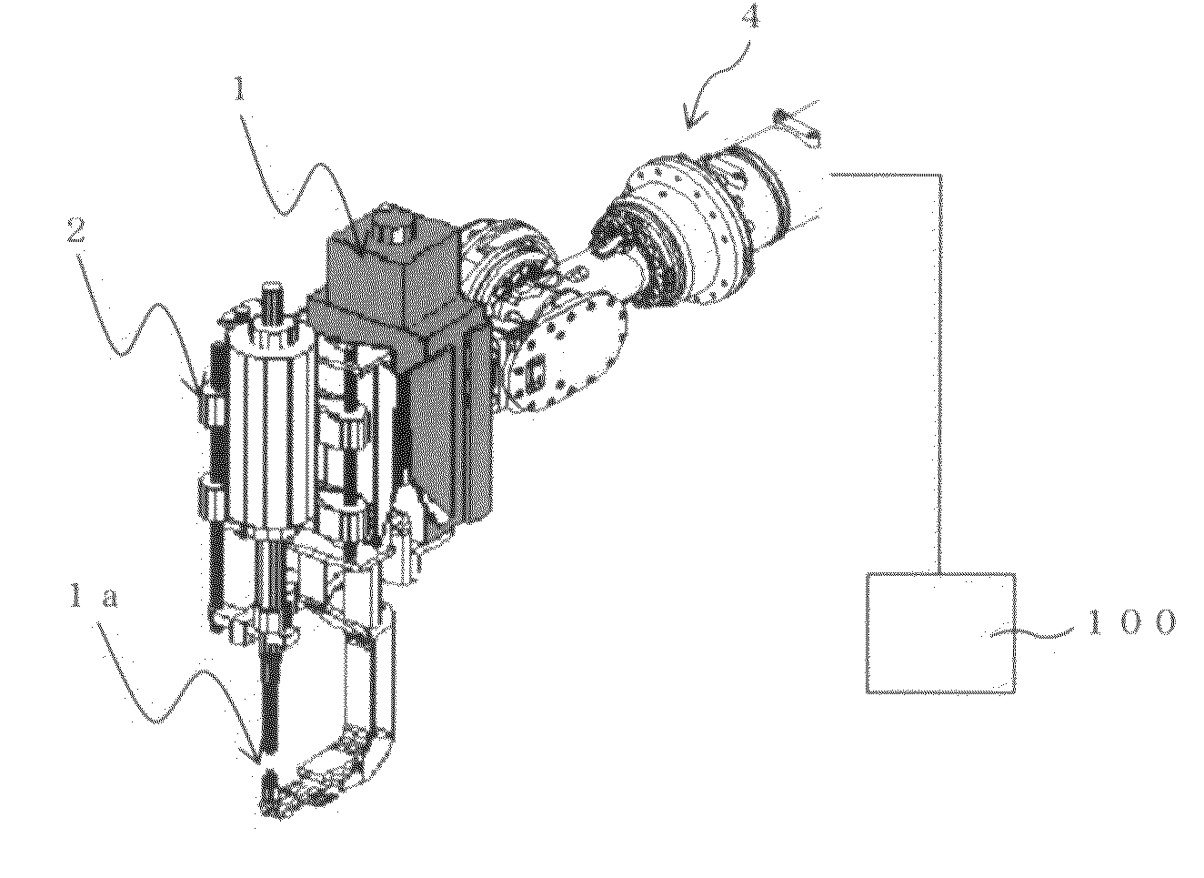
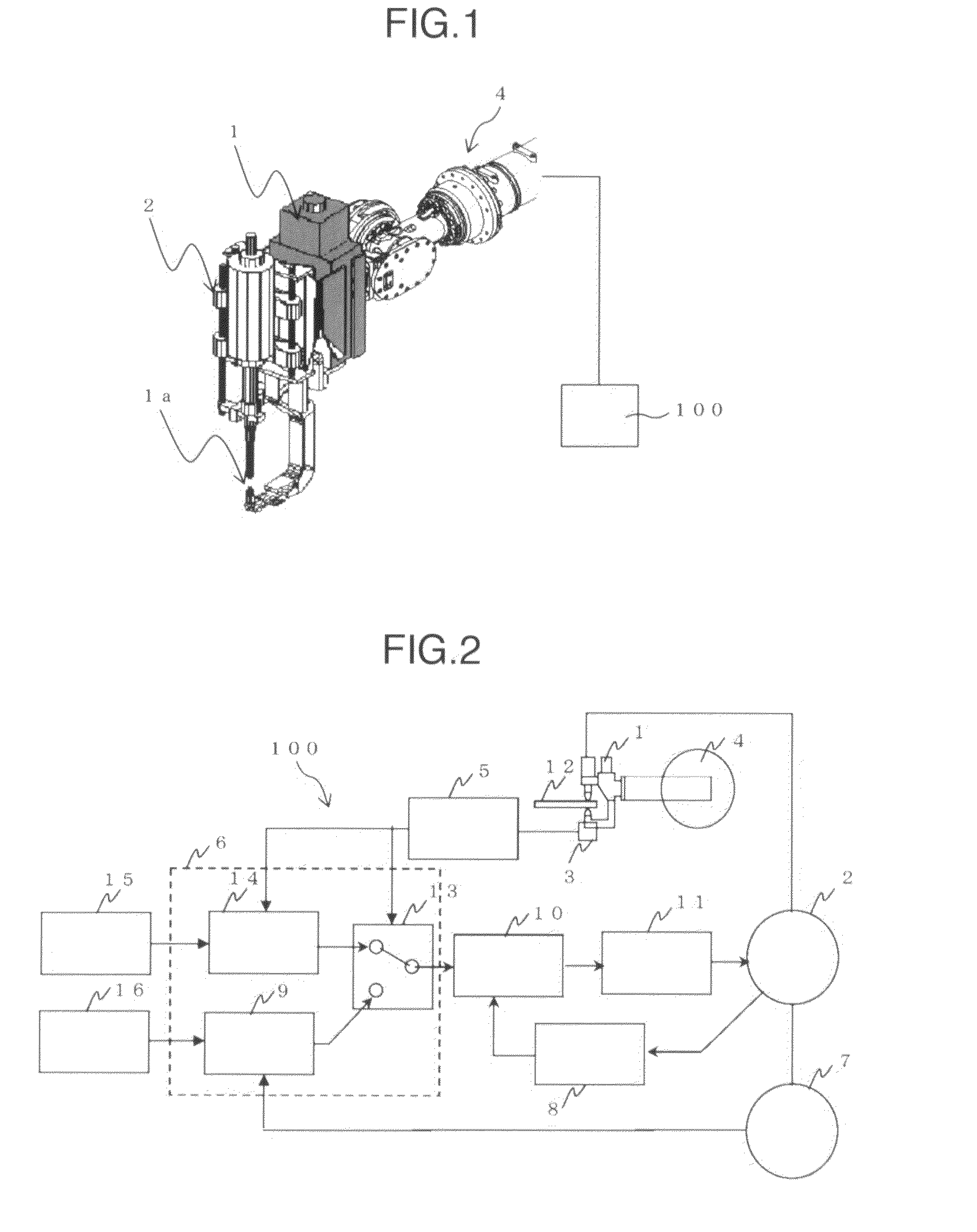
[0026]Referring to FIG. 1, a spot welding system according to the invention has an electric welding gun 1. The electric welding gun 1 is mounted on a tip end of an articulated robot 4 to be freely changeable of its position and direction. A servomotor 2 is mounted in the welding gun 1 for driving a pair of welding electrodes 1a disposed opposite each other to make them approach each other or detach from each other. Further, a control device 100 is connected to the system for controlling the operation of the welding gun 1 and articulated robot 4.

[0027]The spot welding system of the embodiment has a construction similar to that of conventional systems, except for parts related to work pressing control, and therefore, in the present specification, the electric welding gun 1, articulated robot 4 and parts associated with them will be described no more.

[0028]FIG. 2 illustrates related parts for controlling work pressing force.

[0029]In FIG. 2, the electric welding gun 1 and the articulate...

second embodiment

[0034]A spot welding system according to the invention will now be described.

[0035]The system of the second embodiment adopts feedforward control in addition to the feedback control of the embodiment of FIG. 2. In this system, the pressing force control circuit of the control device is different from that of the embodiment of FIG. 2, but the other construction is identical with that of the former embodiment and only different parts will be described.

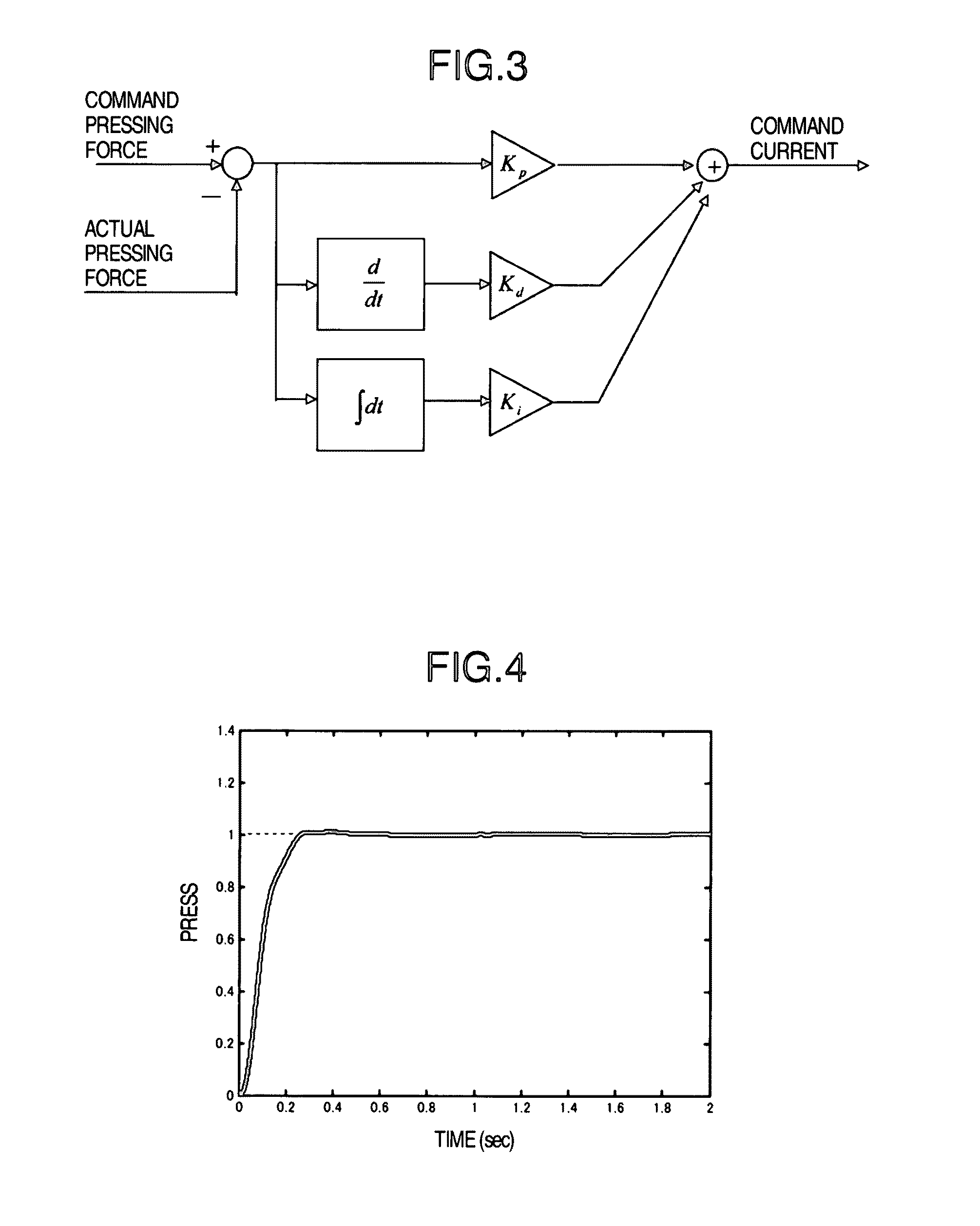
[0036]More specifically, the embodiment of FIG. 2 makes feedback of pressing force information in real time, and pressing current control is performed by a method in which a pressing force current is determined and the servomotor is driven by proportional control of calculating a difference between an actual pressing force and a command pressing force and reducing the difference, by integral control of reducing the steady deviation to zero and by differential control of increasing the speed of reducing the deviation, as illustrated in FI...


PUM

PropertyMeasurementUnit
pressing forceaaaaaaaaaa
currentaaaaaaaaaa
clamping-pressing forceaaaaaaaaaa

Abstract

A spot welding system and method where pressing force of a welding electrode applied by driving a servomotor is accurately controlled. The spot welding system has a pair of welding electrodes, a servomotor (2) for driving the welding electrodes and clamping and pressing an article (12) to be welded, and a controller (100) for controlling the welding electrodes and operation of the servomotor. A pressing force detector (3) is provided in order to measure pressing force actually applied to the article (12) to be welded. The controller (100) regulates a driving current to the servo motor (2) based on the measurement value of the pressing force detector (3), controlling the pressing force applied to the article (12).

Description

TECHNICAL FIELD[0001]The present invention relates to spot welding, and more particularly to a spot welding method and system in which pressing force of welding electrodes driven by a servomotor is accurately controlled.BACKGROUND ART[0002]Spot welding is a technique of welding articles to be welded (hereinafter referred to as a work) by clamping and pressing it with a pair of welding electrodes and by applying large current to melt the work. Particularly, there have been widely used electric welding guns in which welding electrodes are driven by a servomotor, because of their advantages that the pressing force can be freely set and also the opening / closing operation can be freely controlled.[0003]Typically, such an electric welding gun is combined with an articulated robot to automate welding operation and is widely used in jointing of automobile bodies and the like.[0004]In the spot welding, in order to maintain a welding quality, work clamping-pressing force must be maintained at...

Claims


Application Information

Patent Timeline
Patent Type & Authority Applications(United States)
IPC IPC(8): B23K11/11
CPCB23K11/255B23K11/115
Inventor MARUYAMA, AKIRA
Owner NACHI-FUJIKOSHI
Learn More