Variable Speed Flap Retraction and Notification

a variable speed and flap technology, applied in the field of aircraft control, can solve problems such as the addition of pilot workload

Active Publication Date: 2009-12-10
ASTRONICS ADVANCED ELECTRONICS SYST
View PDF7 Cites 18 Cited by
  • Summary
  • Abstract
  • Description
  • Claims
  • Application Information

AI Technical Summary

Benefits of technology

[0012]The present invention provides methods for automatically determining whether to raise the flaps slowly with a single actuation of the flap switch under full engine power. It can also give the pilot an alert (e.g., audible, visual, or both) if the flaps are not retracted while full engine power is applied. The methods can function withi

Problems solved by technology

However, this is additional workload for

Method used


Image

  • Variable Speed Flap Retraction and Notification
  • Variable Speed Flap Retraction and Notification
  • Variable Speed Flap Retraction and Notification

Examples


Embodiment Construction

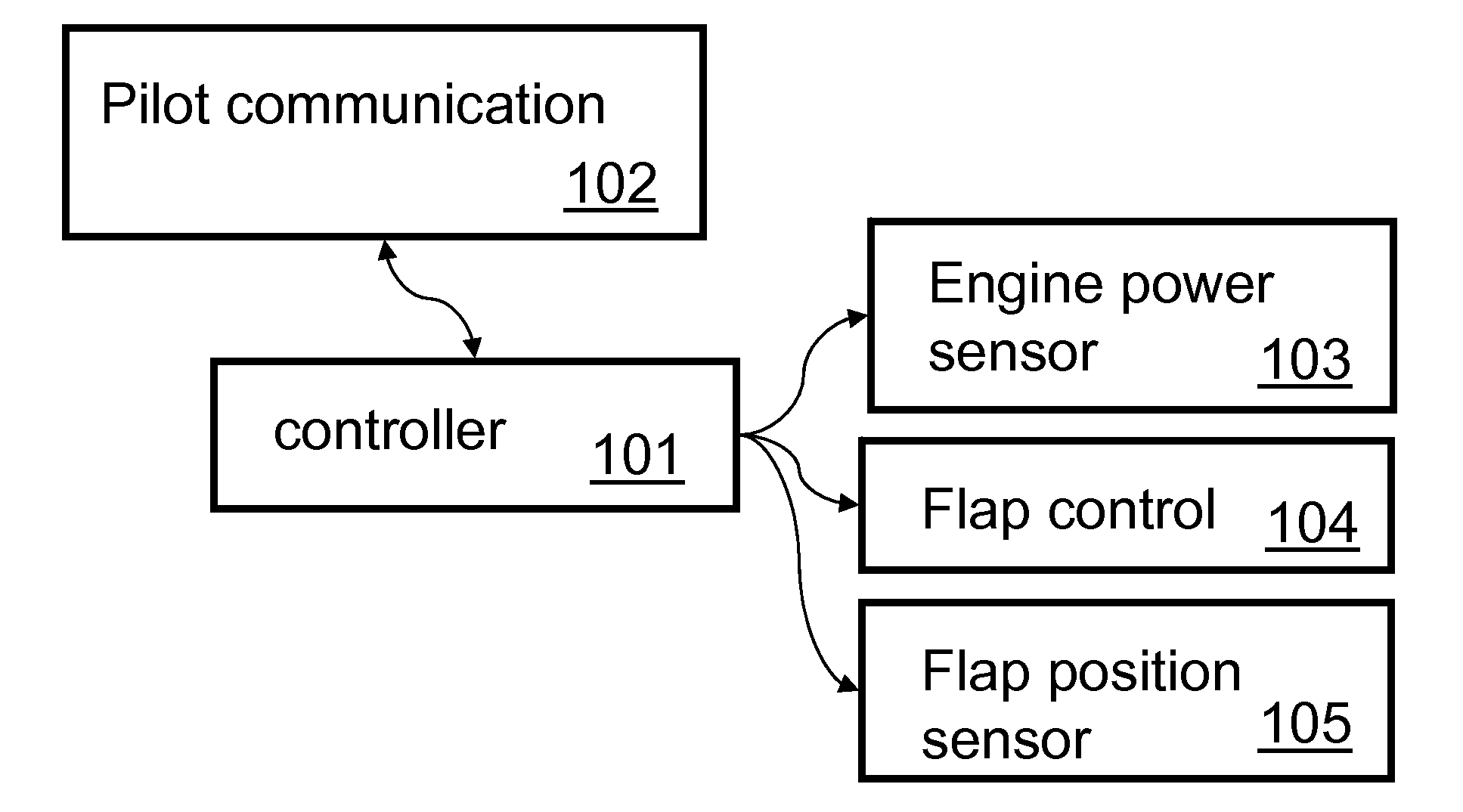
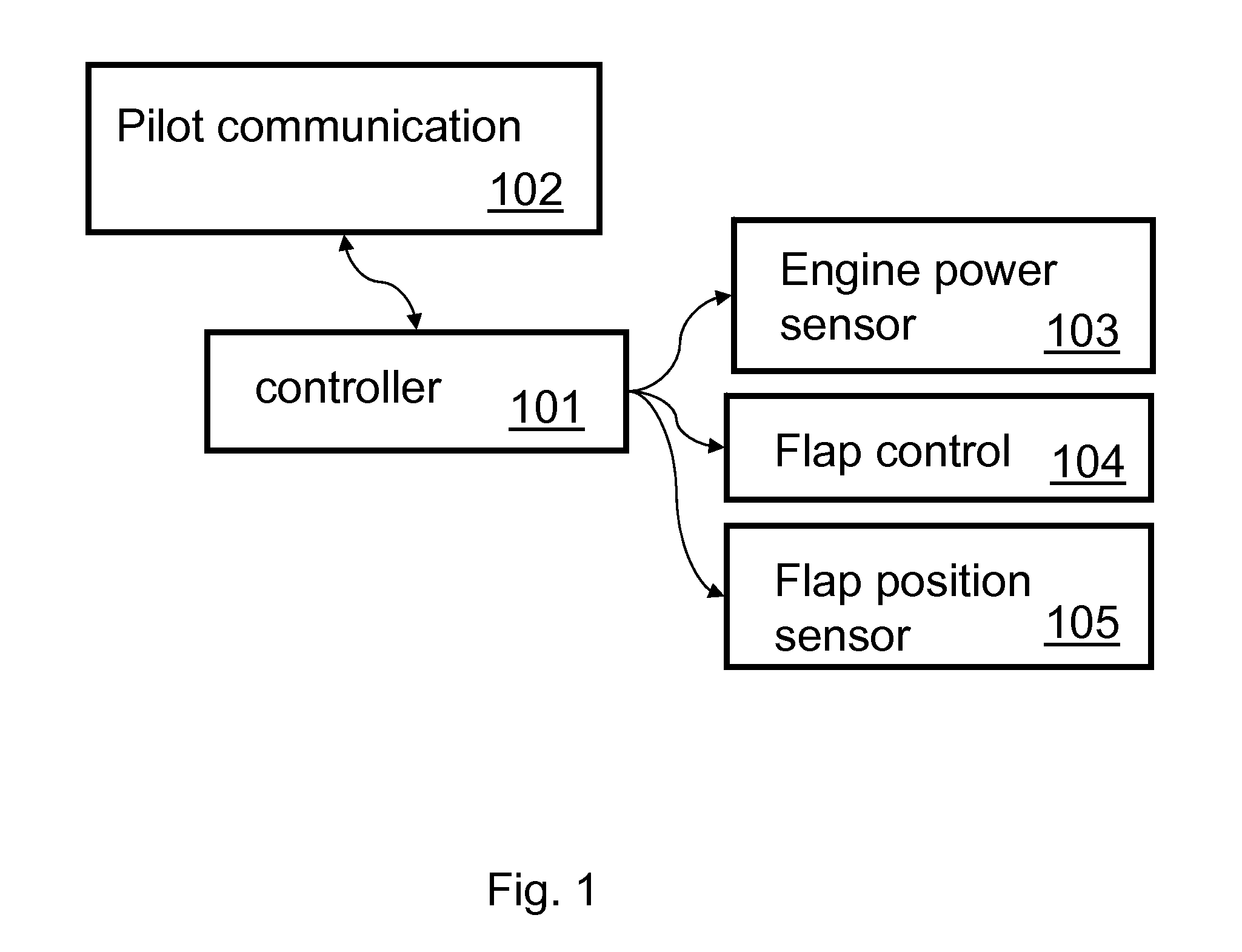
[0017]FIG. 1 is a schematic illustration of an example embodiment of the present invention. The aircraft's flaps are controlled by a flap motor controller 104 such as those known in the art and interfaced with a controller. The position of the aircraft's flaps can be sensed by flap position sensors 105, which in some embodiments can be integrated with the flap motor controller. An engine power sensor 103 senses the output power of the engine, for example by sensing RPM of a piston engine or N1% of a turbine engine. A controller 101 accepts input from the flap position sensors 101 and the engine power sensor 103, and from a pilot input system 102, and provides control signals to the flap motor controller 104. The pilot input system 102 can comprise a voice recognition facility, programmable (or “soft”) buttons such as can be implemented with a touch sensitive display, or a manual switch such as a switch with “up” and “down” momentary contacts and a rest position where neither the “up...


PUM


Abstract

The present invention provides systems and methods for controlling the speed of flap retraction on aircraft, and alerts to the pilot of potentially unsafe flap position. The invention accepts direction from a pilot and senses operation of the aircraft to determine appropriate flap position and flap retraction speed.

Description

CROSS-REFERENCE TO RELATED APPLICATIONS[0001]This application claims the benefit of U.S. provisional application 60 / 853,712, filed Oct. 23, 2006, which is incorporated herein by reference. This application claims the benefit as a continuation-in-part of U.S. patent application Ser. No. 11 / 311,060, filed Dec. 19, 2005, which is incorporated herein by reference.[0002]This application is related to the following applications, each of which is incorporated herein by reference:[0003]Aircraft Emergency Handling, U.S. patent application Ser. No. 11 / 875,813, filed on the same date hereof;[0004]Backup Electrical Power System for Solid-State Aircraft Power Distribution Systems, U.S. patent application Ser. No. 11 / 875,815, filed on the same date hereof;[0005]Aircraft Electrical System Evaluation, U.S. patent application Ser. No. 11 / 875,816, filed on the same date hereof;[0006]Aircraft Exhaust Gas Temperature Monitor, U.S. patent application Ser. No. 11 / 875,818, filed on the same date hereof.FI...

Claims


Application Information

Patent Timeline
IPC IPC(8): B64C13/16
CPCB64D45/0005G01D7/00B64D2045/001G01D2207/10
Inventor AUSMAN, MARCDEVRIES, KEVINDOSTAL, JAKE
Owner ASTRONICS ADVANCED ELECTRONICS SYST
Why Eureka
Try Eureka