
Harmonic absorber

a technology of harmonic absorber and harmonic absorber, which is applied in the direction of reducing harmonics/ripples in dc circuits, power conversion systems, electrical apparatus, etc., can solve the problems of insufficient elimination of harmonics from the network, and inability to eliminate the different levels of harmonics added to the network or the different levels of harmonics

Inactive Publication Date: 2009-12-10
GLOBAL ENERJI BVI
View PDF4 Cites 0 Cited by
  • Summary
  • Abstract
  • Description
  • Claims
  • Application Information

AI Technical Summary

Benefits of technology

[0006]The current invention is related to a harmonic absorber, which meets the above-mentioned requirements, eliminates all of the disadvantages and brings certain advantages.
[0008]Another purpose of the invention is to establish a harmonic absorbing structure, which provides flexibility in the system, and without the need for a structural change, takes an additional new harmonic absorber into service, in case the equipment connections, which result in a rise of the harmonic currents, increase in the voltage network.
[0010]Another purpose of the invention is putting forward a harmonic absorber that eliminates all harmonic currents and voltages and reduces the electrical energy drawn from the network and hence, provides a decrease in the costs.
[0011]A further purpose for the invention is creating a harmonic absorber, which, apart from ensuring the reduction of energy losses in the facility where it has been connected, causes the protection of the life times of the equipment that may be damaged from the harmonics.
[0012]Furthermore, the invention is aimed at providing a harmonic absorber that eliminates the power outages caused by harmonic currents and voltages.

Problems solved by technology

These harmonics cause overheating of transformers, conductors and motors.
When investigating the existing harmonic filters or absorbers, they were insufficient for eliminating these harmonics totally from the network.
So they are incapable of eliminating the different levels of harmonics added to the networks or the different levels of harmonics on the currents that different loads create.
But in reality, after the measurements done, this system may only help to eliminate 1% or 2% of the other levels of the harmonics; this means there is no great effect and benefit.

Method used


Image

  • Harmonic absorber
  • Harmonic absorber
  • Harmonic absorber

Examples


Embodiment Construction

[0018]In this detailed explanation, the preferred structuring of the harmonic absorber (eliminator) is explained in an easily understood manner so that it can be better understood, without any limiting influence.

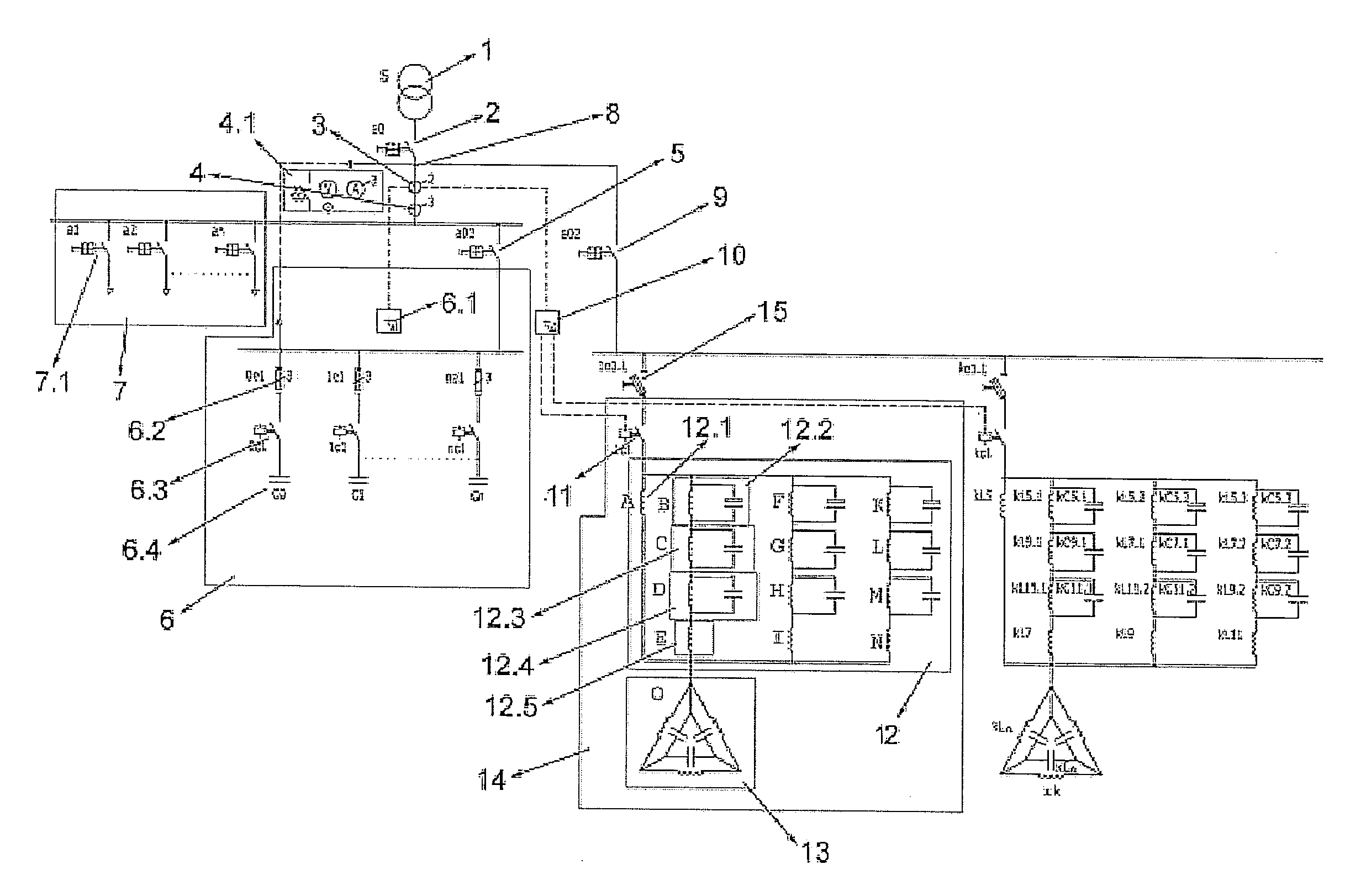
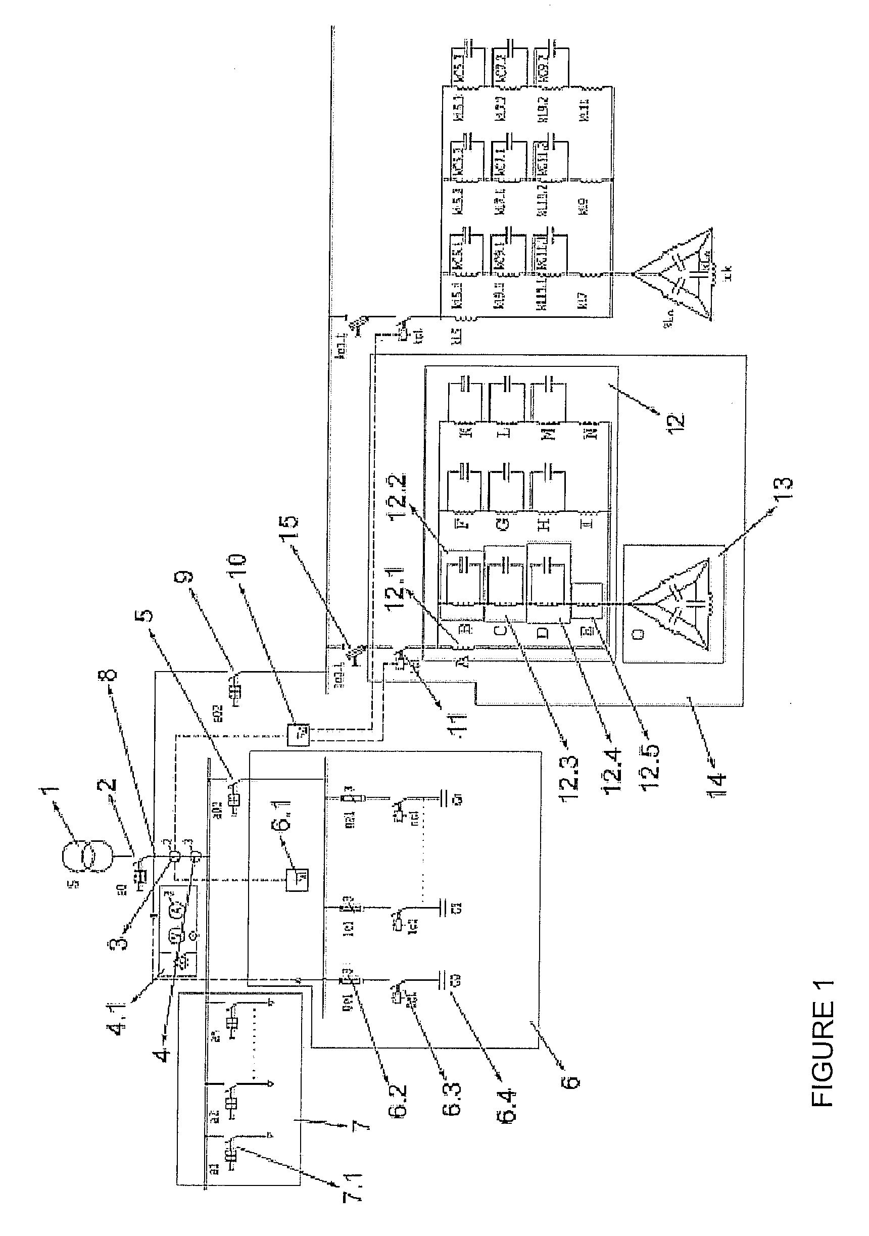
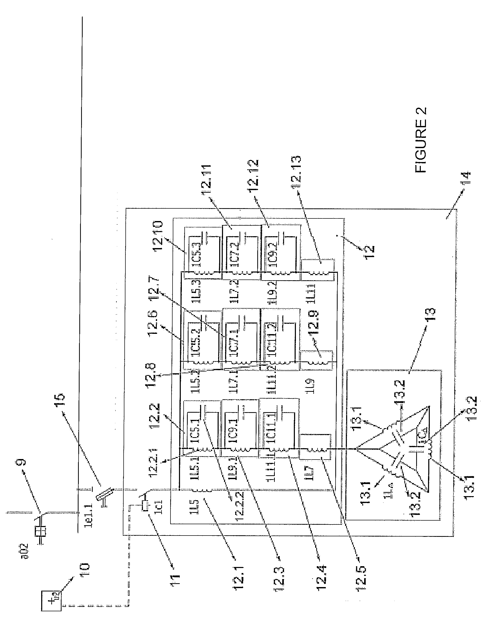
[0019]There is a protection switch (9) selected according to the total value of the harmonic currents, in the circuit acting as a protection element, which opens the circuit without damaging the circuit, and consequently the elements that may occur due to the increasing harmonics in the circuit. Moreover, for the safety of the whole system, a main switch (2) should be included as a protection element. The connection point (8) of this element (2) is very important for the subject of the invention, the harmonic absorber (14), and is right after the current transformers (3, 4) and the connection points of the other relays (6.1, 10), i.e. the distribution point of the current drawn from the network. In other words, one end of the switch (2) should definitely be connected to the ...


PUM


Abstract

This is a harmonic absorber (14) for eliminating the harmonics occurring due to unbalanced loads in a network transformer (1), a power factor correction system (6) to correct the cos φ value of the system to which it has been connected and an electrical system comprising electrical loads (7), and it contains at least one harmonic hole circuit (13), which consists of power reactance inductors (13.1) and power capacitors (13.2), and a harmonic separating circuit (12), which separates the harmonics existing in the network from the other components in the network and then, in order to achieve the elimination of each individual harmonic achieved in this manner, applies them to the mentioned hole circuit (13).

Description

FIELD OF THE INVENTION[0001]This invention is based on a system which eliminates the harmonic voltage and eliminates the harmonic currents which occur in low voltage networks.BACKGROUND OF THE INVENTION[0002]Harmonics are the periodic distortions caused on the sinusoidal waves related to current, voltage or power. It is accepted that their amplitudes are a combination of waveform, different frequencies and the various sinusoidal waves. Harmonics are mainly the results of the non-linear loads of adjustable motor speed drivers or direct current power supplies of computers and televisions. These harmonics cause overheating of transformers, conductors and motors.[0003]When investigating the existing harmonic filters or absorbers, they were insufficient for eliminating these harmonics totally from the network. These products, which are mainly based on dynamic and passive harmonic filters, are widely distributed in the market. The passive ones are designed to eliminate only a certain leve...

Claims


Application Information

Patent Timeline
IPC IPC(8): H02M1/12
CPCY02E40/40H02J3/01
Inventor ISLEYEN, KEMAL
Owner GLOBAL ENERJI BVI
Learn More