Image sensors with improved angle response

Active Publication Date: 2009-12-10
OMNIVISION TECH INC
View PDF59 Cites 7 Cited by
  • Summary
  • Abstract
  • Description
  • Claims
  • Application Information

AI Technical Summary

Problems solved by technology

However, this is undesired as it reduces the amount of light that can be sensed by the pixel 30 which reduces the overall sensitivity of the image sensor 10 and ultimately the sensitivity of camera in which it is included.
Referring to FIG. 6, if the incident light ray angle is sufficiently large, the focal point shifts far enough from the center of the aperture 50 to cause a fraction of the light to be blocked by the light shield 40 resulting in absorption or reflection losses.
Thus, this method works best in the case of a fixed lens system but the extent of the angle response improvement is still limited.

Method used


Image

  • Image sensors with improved angle response
  • Image sensors with improved angle response
  • Image sensors with improved angle response

Examples


Embodiment Construction

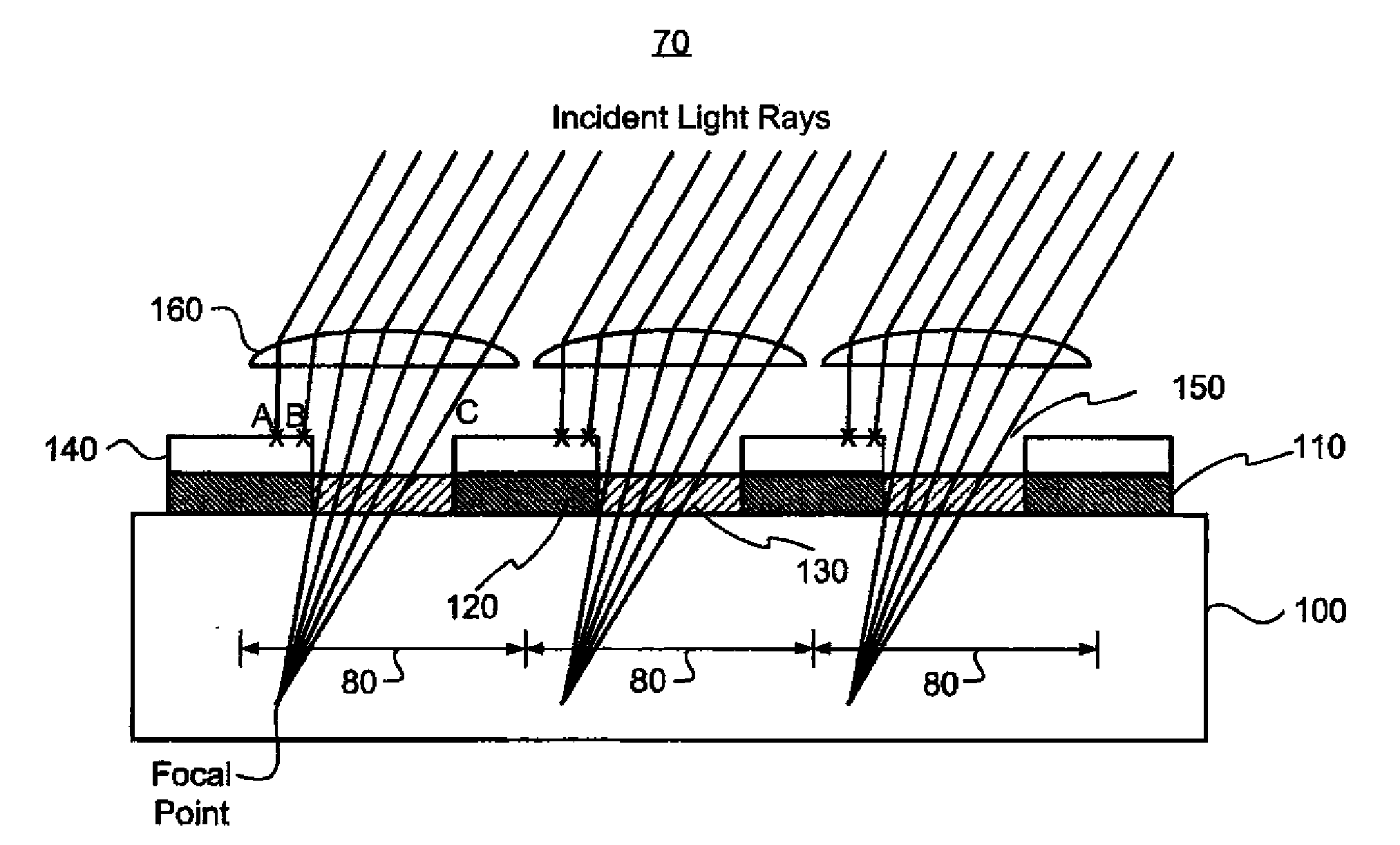
[0027]Referring to FIG. 9, there is shown the image sensor 75 of the present invention having a plurality of pixels 85 arranged in a two-dimensional pixel array 90, although a one-dimensional array may also be used. The image sensor 70 is typically either a full-frame charge-coupled device or a frame transfer charge-coupled device. Referring to FIG. 10, the image sensor 70 of the present invention includes a substrate 100 in which is positioned the plurality of pixels 85. It is noted that the substrate 100 may consist of one type doping (either n type or p type), or it may consist of one doping type with varying concentrations, or more than one doping type in which there is a combination of n type and p type. A transparent layer 110 spans and is positioned on the substrate and includes a polysilicon portion 120 and an ITO portion 130, which is more transparent than the polysilicon portion 120. A light shield 140, which includes a plurality of apertures 150 therethrough, is disposed ...


PUM


Abstract

An image sensor includes a substrate having a plurality of photosensitive areas, a light shield positioned spanning the photosensitive areas in which light shield a plurality of apertures are formed, and a plurality of microlens each disposed centered on one of the apertures such that a focal point of the incident light through each microlens is substantially extended into the substrate to a point where a portion of the incident light directed onto the periphery of each microlens is blocked by a light shield.

Description

FIELD OF THE INVENTION[0001]The present invention generally relates to image sensors having microlenses and, more particularly, to such image sensors having microlenses that focuses incident light deep into the substrate and whose effect is to maintain sensitivity at large incident light angles.BACKGROUND OF THE INVENTION[0002]Referring to FIGS. 1 and 2, image sensor 10 includes a substrate 15 in which there is an array of pixels 20, and each pixel 30 is photosensitive. Referring now only to FIG. 2, depending on the architecture of the pixel 30, some regions of the pixel 30 may be intentionally shielded from light to improve optical isolation between adjacent pixels 30. In some cases, the light is inadvertently blocked as a result of the types of materials used to operate the pixel 30, such as control lines. For example, in interline CCD and CMOS image sensor pixels 30 dedicate a portion of the pixel area for reading out an image while another portion integrates the next image. This...

Claims


Application Information

Patent Timeline
IPC IPC(8): H04N5/225H01L27/148
CPCH01L27/1485H01L27/14818
Inventor MEISENZAHL, ERIC J.
Owner OMNIVISION TECH INC
Why Eureka
Try Eureka