
Laminated Glass with Shade Band

Active Publication Date: 2009-12-10
NIPPON SHEET GLASS CO LTD
View PDF5 Cites 13 Cited by
  • Summary
  • Abstract
  • Description
  • Claims
  • Application Information

AI Technical Summary

Benefits of technology

[0012]In view of the foregoing, an object of the present invention is to provide a laminated glass which reduces light transmittance loss of a certain region thereof at a predetermined wavelength, particularly within a near-IR (750 to 1,000 nm) range and which facilitates provision of an optical instrument employing the near-IR light without partial substitution of an intermediate film.

Problems solved by technology

Since the shade band considerably lowers the light transmittance within a range of visible light to IR light, the shade band reduces sensitivity of a provided photoreceptor to the light passing through the shade band.
However, the method disclosed in Japanese Patent Publication (kokoku) No. 48-81736 has a drawback.
Thus, during the course of sticking with two glass sheets by such an intermediate film, complete degassing becomes difficult, and air bubbles remain in the space between the inner surfaces of the glass sheets.
However, this approach is a cumbersome step, which is problematic.
When the approach disclosed in the pamphlet of WO03 / 059837 is employed, a region of the intermediate film to be given higher transmittance must be substituted by a high-transmittance intermediate film part, which is also a problematically cumbersome step.
However, when the method disclosed in Japanese Patent Application Laid-Open (kokai) No. 2002-173347 is employed, IR-shielding microparticles contained in the intermediate film make the near-IR (750 to 1,000 nm) light transmittance poor.
Thus, when such a pigment is employed, near-IR light cannot completely be received, in the case where an optical instrument employing near-IR light is provided on the interior surface of the glass pane.

Method used


Image

  • Laminated Glass with Shade Band
  • Laminated Glass with Shade Band
  • Laminated Glass with Shade Band

Examples


example 1

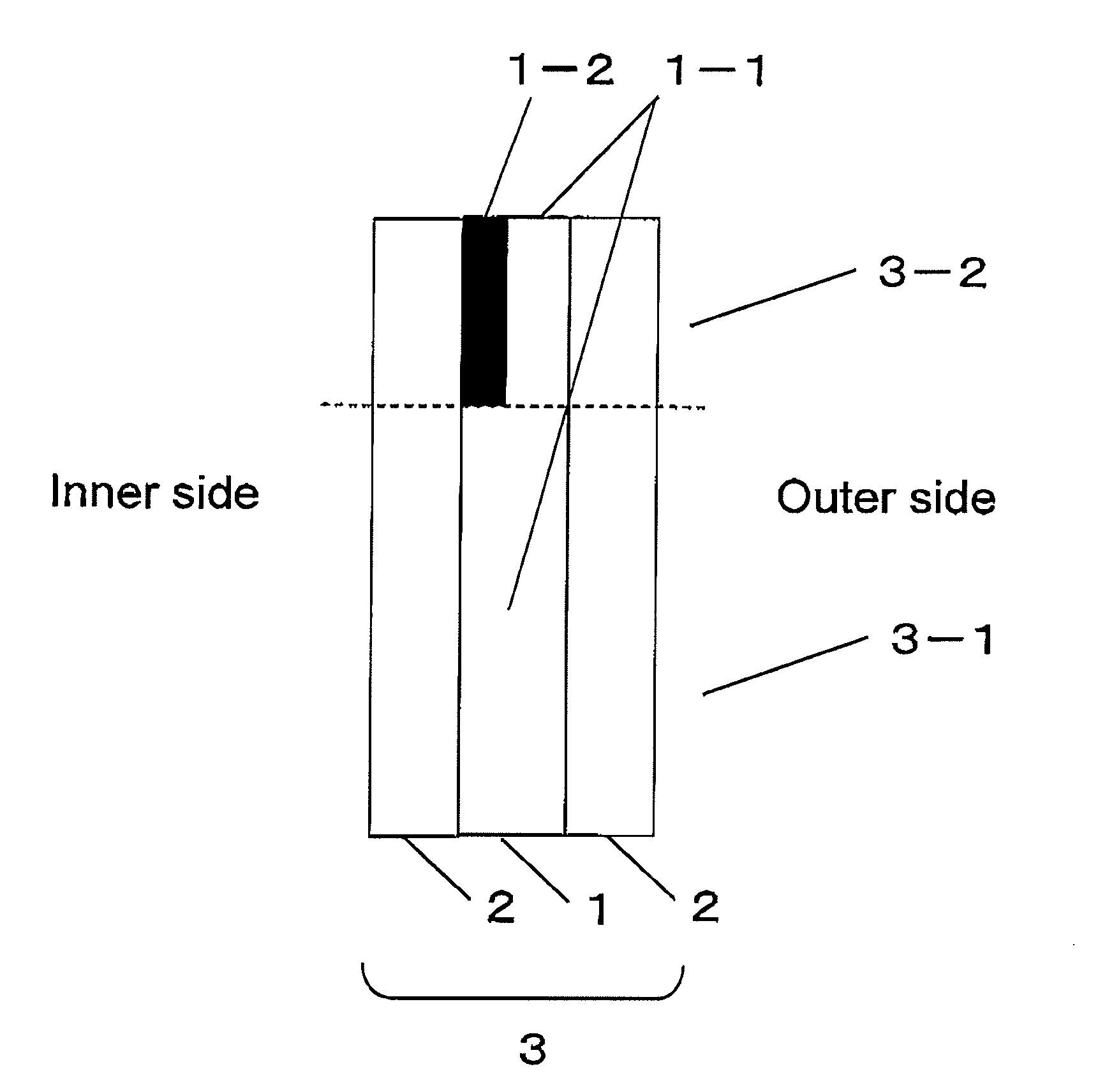
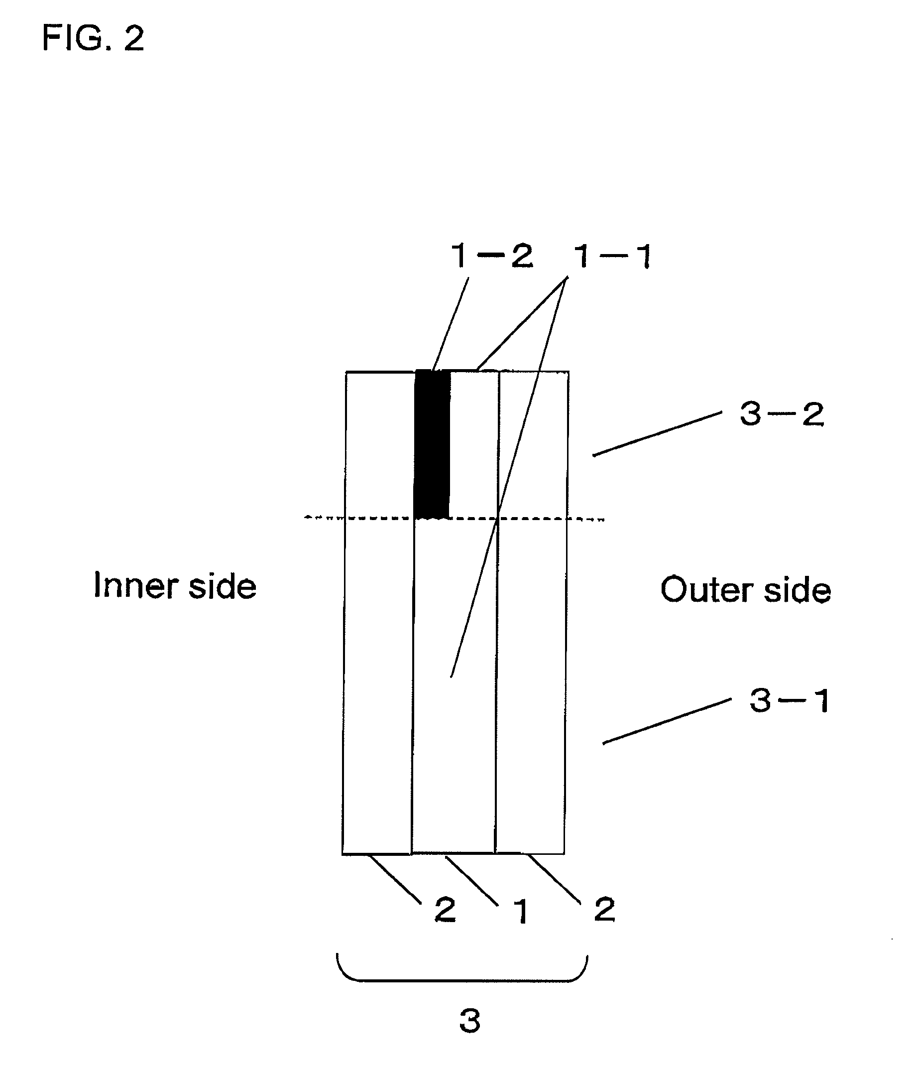
[0074]A belt-like region of a rectangular piece of intermediate film (thickness: 0.76 mm) (Saflex, product of Solutia Japan) along a longer side was colored green by use of a dye. The thus-colored piece was employed as an intermediate film for laminated glass.

[0075]Two rectangular green glass sheets (thickness: 2.1 mm) were stuck together with the mediation of the above-produced intermediate film for laminated glass. Sticking of the two glass sheets by use of the intermediate film was performed through the aforementioned conventional technique.

[0076]The light transmittance of the thus-produced laminated glass (first and second regions) was measured by means of a spectrophotometer UV 3100 PC (Shimadzu Corporation) over a wavelength range of 300 to 1,800 nm. FIG. 1 shows the results. Furthermore, visible light transmittance and light transmittance with respect to light beams (wavelengths: 700, 750, 875, and 1,000 nm) were also measured. The results are shown in FIG. 5 and Table 1.

example 2

[0077]The procedure of Example 1 was repeated, except that clear glass sheets were used instead of the green glass sheets employed in Example 1, to thereby produce a laminated glass.

[0078]The measurement was performed in a manner similar to that of Example 1, and the results are shown in FIG. 6 and Table 1.

example 3

[0079]The procedure of Example 1 was repeated, except that the thickness of the green glass sheets was changed from 2.1 mm to 2.3 mm, and an intermediate film (S-LEC, product of Sekisui Chem. Co., Ltd.) was colored by a dye to form a blue band, to thereby produce a laminated glass.

[0080]The measurement was performed in a manner similar to that of Example 1, and the results are shown in FIG. 7 and Table 1.


PUM

PropertyMeasurementUnit
Fractionaaaaaaaaaa
Fractionaaaaaaaaaa
Fractionaaaaaaaaaa

Abstract

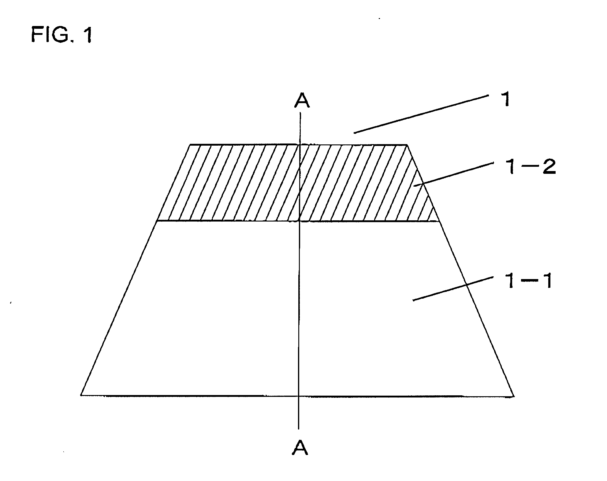
An object of the present invention is to provide a laminated glass which reduces light transmittance loss of a certain region thereof at a predetermined wavelength, particularly within a near-IR (750 to 1,000 nm) range and which facilitates provision of an optical instrument employing the near-IR light without partial substitution of an intermediate film. The invention provides a laminated glass for vehicle formed of two glass sheets stuck with a thermoplastic resin film, wherein the laminated glass has a first region and a second region; the second region is provided in a belt-like form along upper side of the laminated glass when the laminated glass is secured onto the vehicle; the first region has a visible light transmittance of 70% or higher; the second region has a visible light transmittance of 5% to 50%; the difference, in a light transmittance within a wavelength range of 750 to 1,000 nm, between the first region and the second region is 5% or less; and the second region has a light transmittance of 25% or higher, within a wavelength range of 750 to 1,000 nm.

Description

BACKGROUND OF THE INVENTION[0001]1. Field of the Invention[0002]The present invention relates to a laminated glass for vehicle and, more particularly to a laminated glass for vehicle used in conjunction with an optical instrument.[0003]2. Background Art[0004]In order to enhance anti-glare and heat-shielding performance, some types of laminated glass for vehicle, particularly those for a windshield, are provided with a colored (green, blue, etc.) band-form shade area (i.e., shade band). Such a shade band is generally formed through coloring a band-form area of an intermediate film for joining glass sheets. By law, a windshield provided with a shade band is required to have an area (vision area) having a visible light transmittance equal to or higher than a predetermined value (e.g., ≧70%). Therefore, a shade band is generally formed in an upper section of a windshield, which is present outside the visible area.[0005]In recent years, there has been proposed an intermediate film for la...

Claims


Application Information

Patent Timeline
IPC IPC(8): G02B5/20
CPCB32B17/10036B32B17/10339B32B17/10761B60J1/00Y10T428/162C03C4/085C03C17/007C03C27/10C03C2217/485C03C4/02
Inventor MATSUSHITA, YOSHIMITSUMARUYAMA, TORUOKAMOTO, HIDEKI
Owner NIPPON SHEET GLASS CO LTD
Learn More