Method and apparatus for reducing differential mode and common mode reflections in motor drives

a technology of motor drive and differential mode, applied in the field of three-phase ac motor drive, can solve problems such as premature bearing failur

Inactive Publication Date: 2009-12-10
ROCKWELL AUTOMATION TECH
View PDF6 Cites 24 Cited by
  • Summary
  • Abstract
  • Description
  • Claims
  • Application Information

AI Technical Summary

Benefits of technology

[0037]It is thus an object of one embodiment of the invention to permit the invent...

Problems solved by technology

Common mode voltage and current transients can cause premature bearing failure by creat...

Method used


Image

  • Method and apparatus for reducing differential mode and common mode reflections in motor drives
  • Method and apparatus for reducing differential mode and common mode reflections in motor drives
  • Method and apparatus for reducing differential mode and common mode reflections in motor drives

Examples


Embodiment Construction

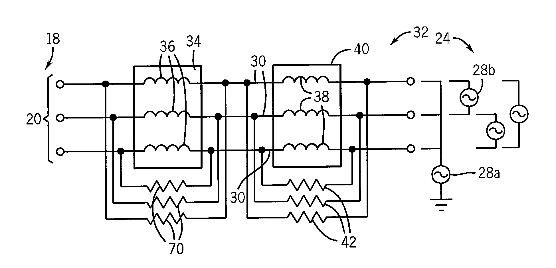
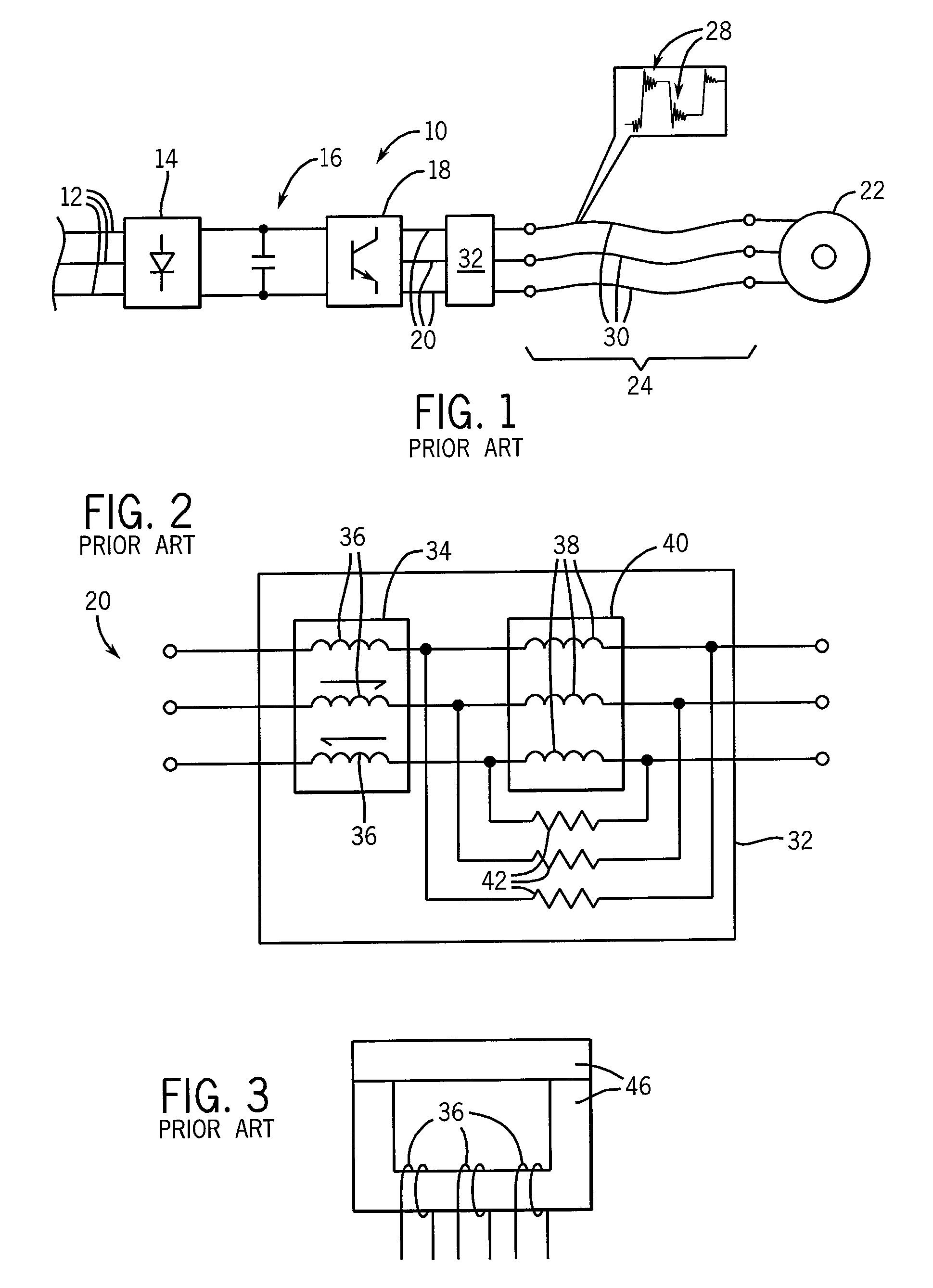
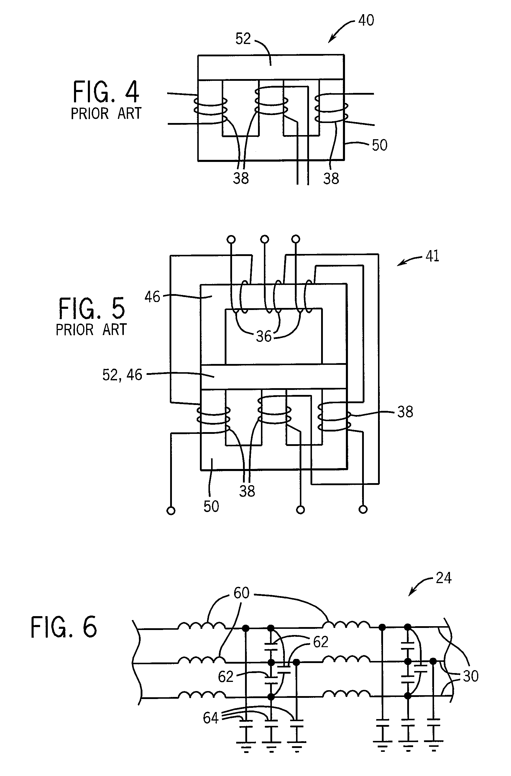
[0048]Referring now to FIG. 6, the conductors 30 of power cable 24 may have an intrinsic inductance represented by discrete inductors 60 distributed in series along the length of each power conductor 30.

[0049]A differential mode impedance will be determined by these inductors 60 together with capacitors 62 passing between each conductor 30 and its neighbor representing the distributed capacitance among the conductors 30, and capacitors 64 passing from each conductor 30 to ground typically presented by a shield around the conductors 30.

[0050]The common mode characteristic impedance of the power cable 24, in contrast, will be determined by inductors 60 together with capacitors 64 passing from each conductor 30 to ground.

[0051]In practice, the differential mode impedance is measured from one end of any conductors 30 to the other two conductors connected to each other at that end and with all three conductors connected to each other at the other end. This differential impedance measurem...


PUM


Abstract

A filter device reduces reflections on power lines from the motor drive to AC motors by providing a differential mode choke in series with a common mode choke both shunted by resistances tailored to the characteristic impedance of the power cable for differential mode and common mode reflections respectively. By treating both common mode based and differential mode based reflections, superior transient control and motor drive performance may be obtained.

Description

CROSS-REFERENCE TO RELATED APPLICATIONS_ _ _ STATEMENT REGARDING FEDERALLY SPONSORED RESEARCH OR DEVELOPMENT_ _ _ BACKGROUND OF THE INVENTION[0001]The present invention relates to three-phase AC motor drives and particularly to a filter device for power lines communicating between such drives and a connected motor.[0002]Common AC induction motors use three-phase electrical power connected to stator windings of the motor. Each stator winding receives a different conductor of a three-phase power transmission line, where each conductor communicates an AC power waveform shifted with respect to the other conductors by plus and minus 120°.[0003]Referring to FIG. 1, the motor 22 may connect directly to a power grid or, as shown, connect to a solid-state motor drive 10. In this latter case, the motor drive 10 will receive three-phase power 12 from the power grid at a rectifier 14 and the rectifier 14 will convert the received three-phase AC power into DC power on a DC link 16. The rectifier...

Claims


Application Information

Patent Timeline
IPC IPC(8): H02H3/22H01F27/34
CPCH01F2017/0093H02M2001/123H02M1/126H02H9/005H02M1/123
Inventor TALLAM, RANGARAJAN M.SKIBINSKI, GARY L.
Owner ROCKWELL AUTOMATION TECH
Why Eureka
Try Eureka