Light source module for a light fixture

Active Publication Date: 2009-12-10
MARTIN PROFESSIONAL
View PDF17 Cites 13 Cited by
  • Summary
  • Abstract
  • Description
  • Claims
  • Application Information

AI Technical Summary

Benefits of technology

[0026]By changing the speed of the blowing means, the turbulent airflow generated where airstreams meet will be very different. By changing the speed of the air, the most turbulent volumes inside the reflector or the cavity below the reflector will change all the time and the cooling effect w

Problems solved by technology

Especially, if blowing means are placed approximately in the area close to a light source, the temperature of the suction air into a blowing system can be relatively high which will decre

Method used


Image

  • Light source module for a light fixture
  • Light source module for a light fixture
  • Light source module for a light fixture

Examples


Example

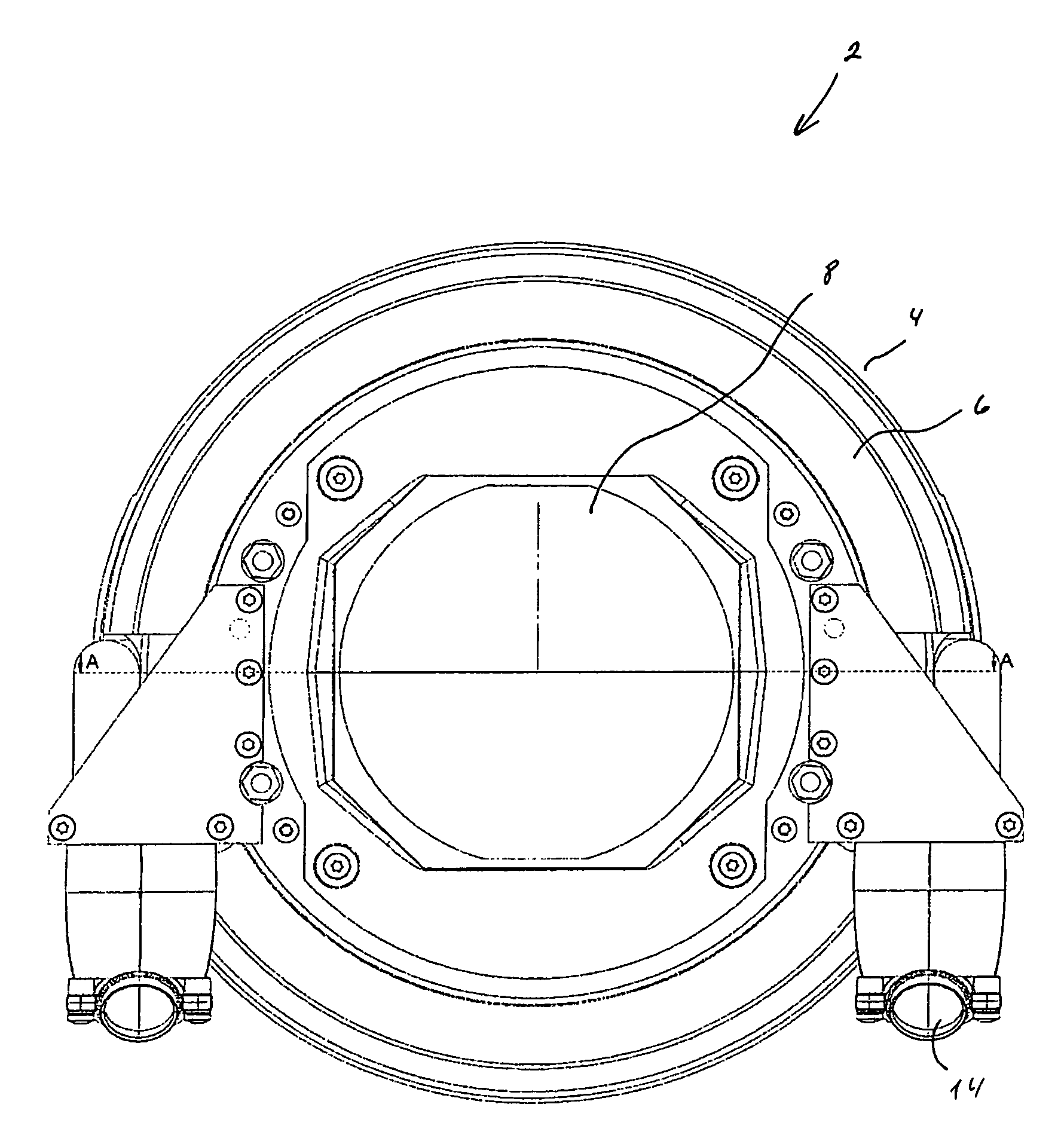
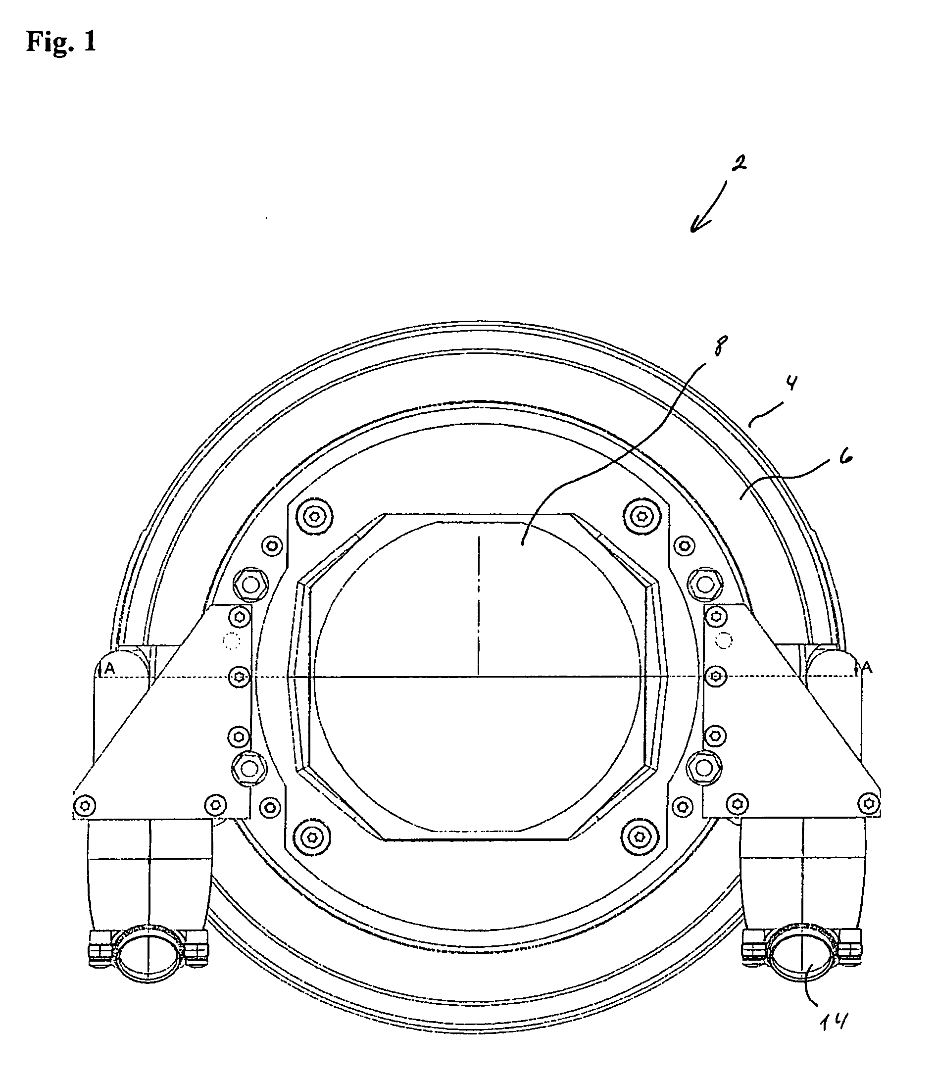
[0033]FIG. 1 shows a light source module 2 seen from the front. The light source module 2 comprises a housing 4 which has a conical side area 6 and an infrared reflecting optical filter 8. Furthermore, air inlet tubes 14 are indicated.

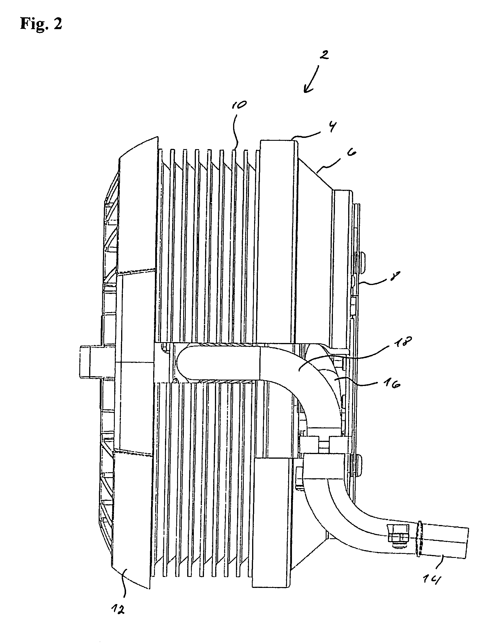
[0034]FIG. 2 shows the light source module 2 for a light fixture seen from the side. In this figure, the housing 4, the conical part 6 and the infrared optical filter 8 are also indicated. Furthermore, dishes 10 and a housing 12 for the light source base are indicated. FIG. 2 also shows a connection tube 14 for an air inlet which continues into a manifold that divides into tubes 16, 18.

[0035]FIG. 3 shows a sectional view of the light source module 2. The light source module comprises the same components as previously described, but especially in this figure the infra red filter 8 is indicated. Furthermore a heat sink is shown that is formed of the dishes 10 and the housing for the light source base 12. The air inlet 14 is also indicated. These air inle...


PUM


Abstract

A method for generating an air stream for cooling a light source, and a light source module for a light fixture with a blower for cooling the light source and the light source base. To achieve highly effective cooling of a lamp in a light fixture or a projector at least one forced air stream is generated by a blower system which blower system can be placed at a distance from the light source module and can be connected from the blower through a tube to a duct which directs an air stream towards the light source. By using a tube for the connection between the blowing unit and the actual place where air stream is to be used for cooling, it is possible to operate the blower in a place where the suction inlet for air into the blowing unit is a relatively cool place.

Description

BACKGROUND OF THE INVENTION[0001]1. Field of the Invention[0002]The present invention relates to a light source module for a light fixture, comprising a light source, which light source is connected through a light source base, which light source module comprises cooling means for cooling the light source and the light source base, which light source module further comprises a dichroic reflector, where at least one heat sink surrounds the dichroic reflector and comprises a number of dishes, which dishes are formed to achieve air gaps there between, which air gaps between the dishes are directed mostly perpendicularly to a center axis for the light source module, which heat sink forms air gap between the heat sink and the dichroic reflector, the heat sink being open towards the air gaps between the dishes.[0003]The present invention relates further to a method for generating an air stream for cooling a light source, by which method the air stream is generated in a radial blower, whic...

Claims


Application Information

Patent Timeline
IPC IPC(8): F21V29/02F21V29/505
CPCG03B21/16F21V29/02F21V29/67F21V29/70
Inventor BJERRE, FLEMMING FREESE
Owner MARTIN PROFESSIONAL
Why Eureka
Try Eureka