Planar illumination device

a technology of illumination device and planar plane, which is applied in the direction of lighting and heating apparatus, mechanical apparatus, instruments, etc., can solve the problems of difficulty in realizing a backlight unit having a thinner thickness, and achieve the effect of reducing thickness, improving light use efficiency, and increasing siz

Active Publication Date: 2009-12-10
FUJIFILM CORP
View PDF12 Cites 30 Cited by
  • Summary
  • Abstract
  • Description
  • Claims
  • Application Information

AI Technical Summary

Benefits of technology

[0065]According to the present invention, the light guide plate is formed into the shape in which the thickness in the direction perpendicular to the light exit surface increases with the increase in distance from the light incident surface. Therefore, light incident on the light incident surface may be sent to a more distant position, the thickness may be reduced, and the light exit surface may be increased in size.
[0066]The rear surface is formed into the curved shape in which the inclined angle relative to the light exit surface reduces with the shift from the first light incident surface or the second light incident surface to the center, and the inclined angle relative to the light exit surface is zero degrees at the center. Therefore, the light use efficiency may be improved.
[0067]The brightness distribution of the light emitted from the light exit surface may be set to be of bell-shaped.
[0068]Even in another aspect of the present invention, the light guide plate is formed into the shape in which the thickness increases with the increase in distance from the light incident surface. Therefore, the light incident on the light incident surface may be sent to a more distant position, the thickness may be reduced, and the light exit surface may be increased in size.
[0069]The light emitting surface of the light source is inclined. Therefore, even when a light source whose light emitting surface area is large is used for a light guide plate whose light incident surface thickness is small, light may be allowed to enter efficiently. That is, the light use efficiency may be improved. When the light emitting surface area is increased, the amount of light emitted from the light emitting surface may be increased.
[0070]In other words, according to the another aspect of the present invention, the light whose brightness or illuminance is high may efficiently be emitted from the light exit surface, and the device may be reduced in thickness.

Problems solved by technology

However, according to the direct underneath type, in view of light amount unevenness, it may be difficult to realize a backlight unit having a thinner thickness, for example, a thickness equal to or smaller than 10 mm.

Method used


Image

  • Planar illumination device
  • Planar illumination device
  • Planar illumination device

Examples


Embodiment Construction

[0131]Hereinafter, planar illumination devices according to embodiments of the present invention are described in detail with reference to the attached drawings.

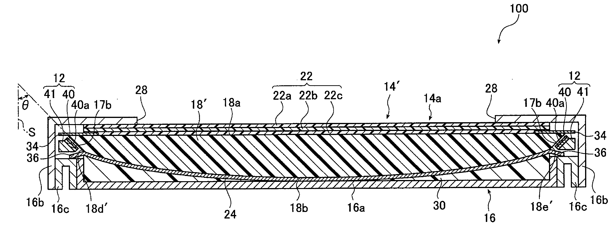
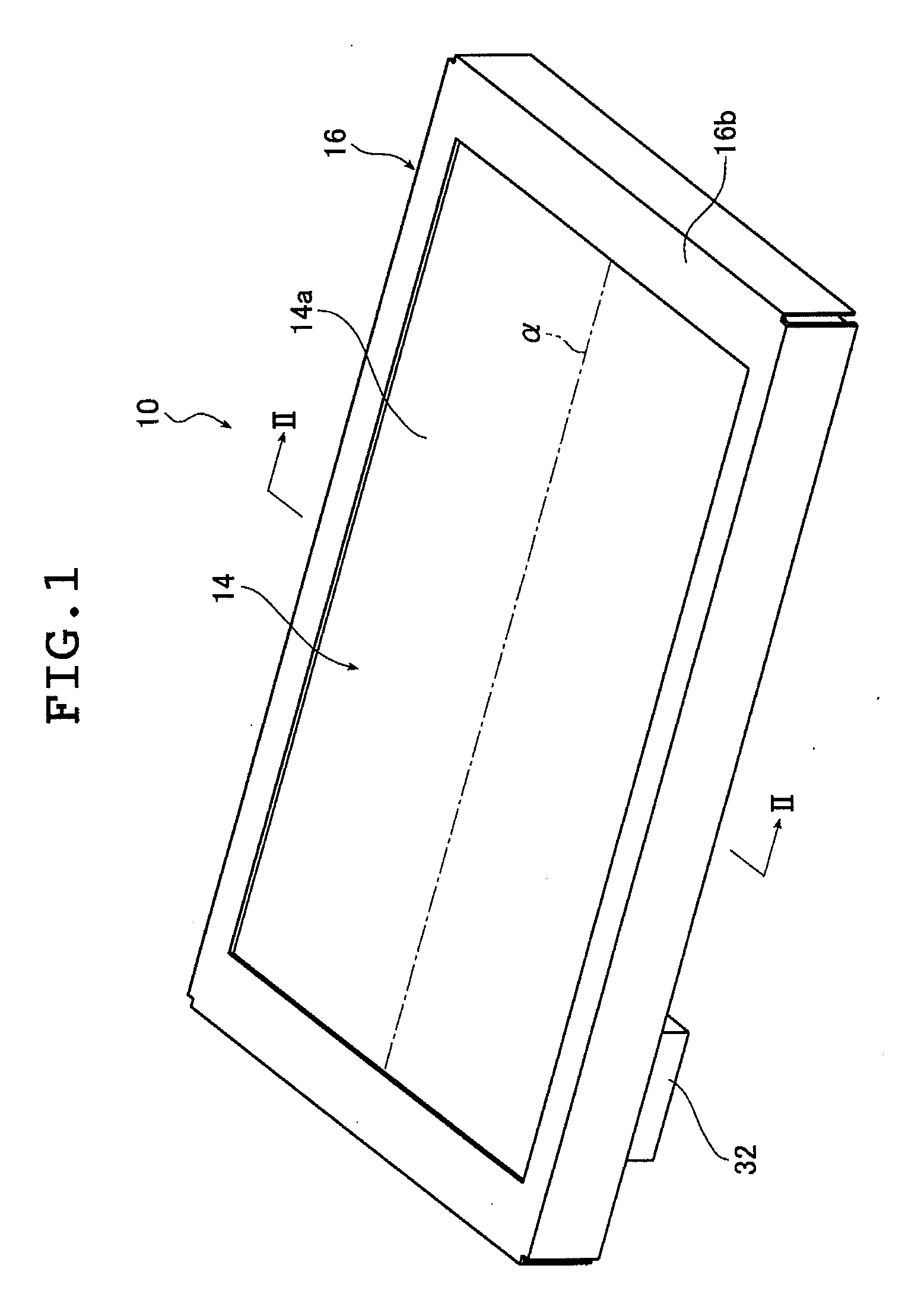
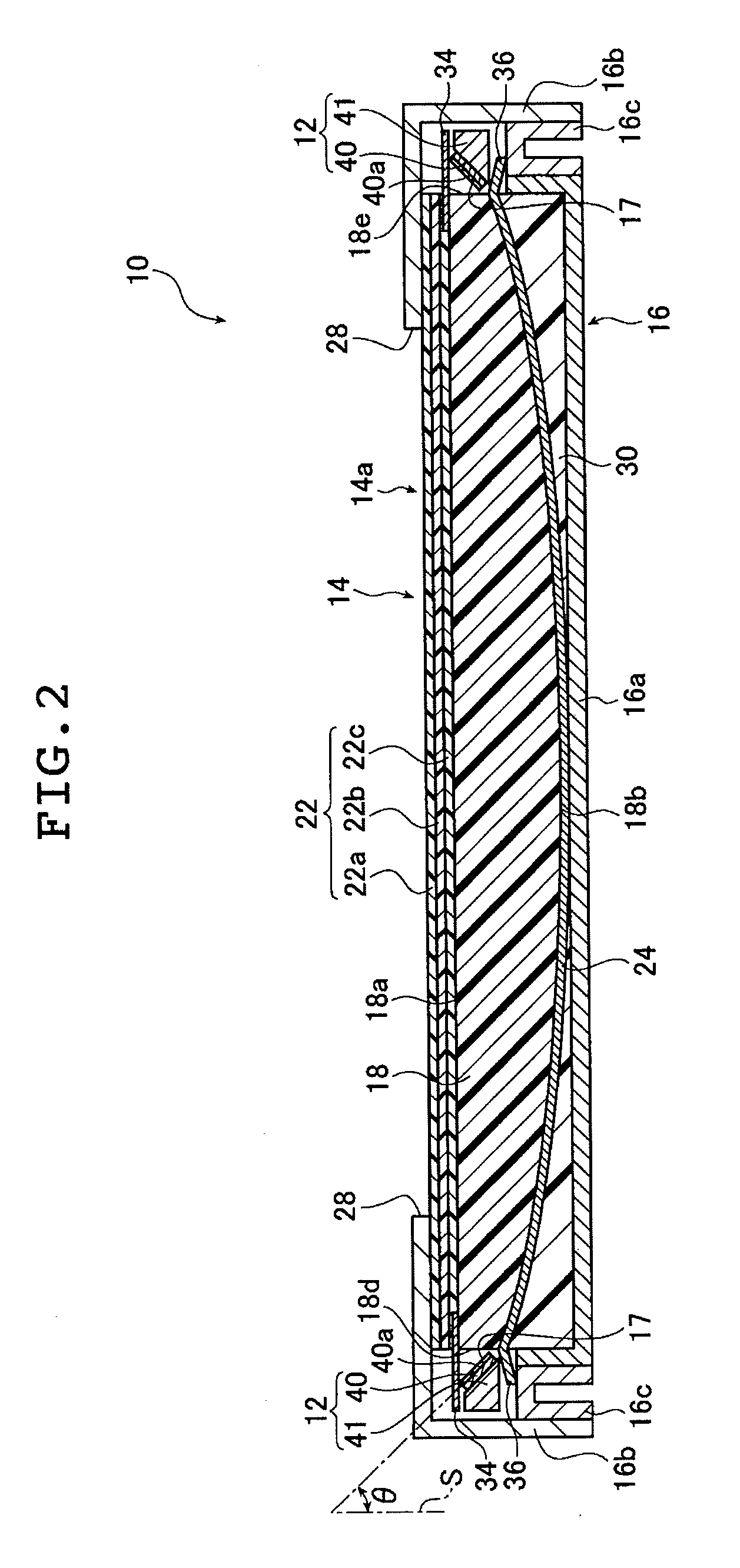
[0132]FIG. 1 is a perspective view illustrating a planar illumination device according to an embodiment of the present invention. FIG. 2 is a II-II line cross sectional view illustrating the planar illumination device illustrated in FIG. 1. FIG. 3 is an enlarged cross sectional view illustrating an enlarged part of the planar illumination device illustrated in FIG. 2.

[0133]In the respective drawings, a planar illumination device 10 includes light sources 12, an illumination device main body 14 for emitting uniform light from a rectangular-shaped light exit surface 14a, fluorescent members 17 each being arranged between each of the light sources 12 and the illumination device main body 14, and a case 16 which accommodates the light sources 12, the illumination device main body 14, and the fluorescent member 17. As described l...


PUM


Abstract

It is an object to provide a planar illumination device that is thin and light weight, and can emit uniform illumination light with little brightness unevenness and can be enlarged in size. It is to provide a planar illumination device comprising: a first light source and a second light source which are arranged at predetermined intervals; and a light guide plate which is arranged between the first light source and the second light source and has: a light exit surface; a first light incident surface which is opposed to the first light source and includes a side of the light exit surface; a second light incident surface which is opposed to the second light source and includes an opposite side to the side; and a rear surface which is formed to be opposed to the light exit surface, wherein a cross section on a plane perpendicular to the side, of the rear surface of the light guide plate has a curved line in which a distance from the light exit surface increases with a shift from the first light incident surface and the second light incident surface to a center, an inclined angle relative to the light exit surface reduces with a shift from the first light incident surface or the second light incident surface to the center, and the inclined angle relative to the light exit surface is zero degrees at the center.

Description

TECHNICAL FIELD[0001]The present invention relates to a planar illumination device including a light guide plate for diffusing light emitted from a light source to emit illumination light from a light exit surface, and more particularly, to a planar illumination device which is used as a planar illumination device for illuminating indoors and outdoors, a backlight unit for illuminating a liquid crystal display panel of a liquid crystal display device, or a backlight unit for an advertising panel, an advertising tower, a signboard, or the like.BACKGROUND ART[0002]For a liquid crystal display device, a backlight unit that emits light from a backside of a liquid crystal display panel to illuminate the liquid crystal display panel has been used. The backlight unit is configured by using a light guide plate for diffusing light emitted from a light source for illumination to illuminate the liquid crystal display panel, and optical members such as a prism sheet and a diffusion film for uni...

Claims


Application Information

Patent Timeline
Patent Type & Authority Applications(United States)
IPC IPC(8): F21V8/00
CPCG02B6/0025G02B6/0068G02B6/0046G02B6/0041
Inventor IWASAKI, OSAMU
Owner FUJIFILM CORP
Why Eureka
Try Eureka