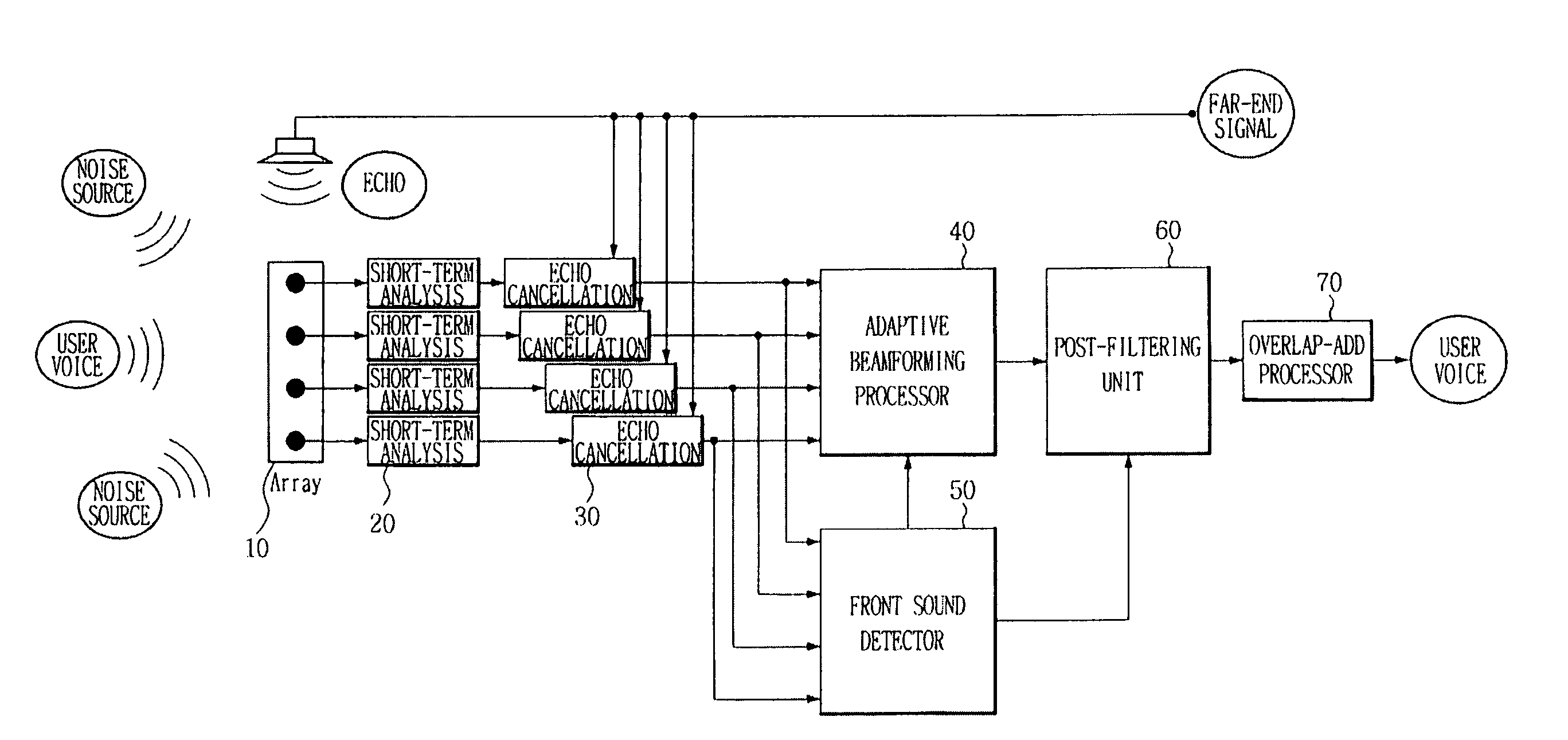
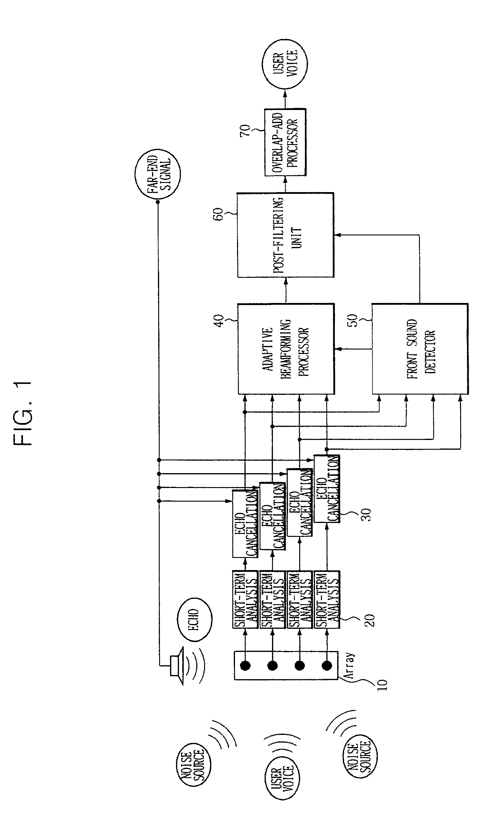
[0024]FIGS. 1 through 6, discussed below, and the various embodiments used to describe the principles of the present disclosure in this patent document are by way of illustration only and should not be construed in any way to limit the scope of the disclosure. Those skilled in the art will understand that the principles of the present disclosure may be implemented in any suitably arranged communication system.
[0025]One condition for improving performance of adaptive beamforming is that adaptation of an adaptive filter used in adaptive beamforming be stopped when a user speaks. This is determined by adaptive mode control.
[0026]FIG. 1 illustrates a block diagram of a directional noise canceling system using a microphone array. The noise canceling system includes at least one microphone 10, a short-term analyzer 20 connected to each microphone, an echo canceller 30, an adaptive beamforming processor 40 that cancels directional noise and turns a filter weight update on or off based on whether or not a front sound exists, a front sound detector 50 that detects a front sound using a correlation between signals of microphones, a post-filtering unit 60 that cancels remaining noise based on whether or not a front sound exists, and an overlap-add processor 70.
[0027]Table 1 shows notations and definitions that will be used in the below description.
TABLE 1 Usage Notation Definition notation definition Common k discrete N noise frequency index m discrete ΦAB cross-power time index spectrum of A and B l frame index μ forgetting factor i microphone {circumflex over ( )} estimation index value, for example, Ŝ is an estimated voice * conjugate w window function Z input signal SNR signal-to-noise ratio Y echo SER signal-to-echo ratio H echo path DFT discrete transfer Fourier function transform X far-end FFT fast Fourier signal transform S voice LMS least mean square Echo Zaec echo-canceled Pfar short-term cancellation signal power of far-end signal η double-talk detection measure Adaptive Zfb fixed E error signal beamforming beamformer output Zsb signal Pgsc power spectrum blocking of reference output noise Zgsc adaptive A signal path beamformer transfer output function Front sound Psrp power of front detection sound Post-filtering ξ a priori SNR λS voice power-spectrum γ a posteriori λN noise SNR power-spectrum
[0028]Although the system in FIG. 1 illustrates at least one microphone 10, that the following examples utilize four microphones 10 in the system. A signal input to each microphone can be expressed by Equation 1:
Zi(k,l)=Yi(k,l)+Ni(k,l),i=1 . . . 4 [Eqn. 1]
[0029]where Z denotes an input signal, Y denotes an echo, N denotes noise, i denotes a microphone index, k denotes a discrete frequency index, and 1 denotes a frame index.
[0030]An echo Yi(k, l) is input to each of the four microphones 10 through each echo path Hi(k), and an echo signal input to each microphone can be expressed by Equation 2:
Yi(k,l)=Hi(k)X(k,l),i=1 . . . 4 [Eqn. 2]
[0031]where Y denotes an echo, H denotes an echo path transfer function, X denotes a far-end signal, i denotes a microphone index, k denotes a discrete frequency index, and 1 denotes a frame index.
[0032]Here, it is assumed that X(k, 1) and N(k,l) are related to each other in Equation 1 and Equation 2.
[0033]Frequency domain analysis for voices input to each microphone 10 is performed through the short-term analyzer 20.
[0034]For example, one frame corresponds to 256 milliseconds (ms), and a movement section is 128 ms. Therefore, 256 ms is sampled into 4,096 at 16 Kilohertz (Khz).
[0035]When a Hanning window is applied, Equation 3 can be used.
[0036]A Hanning window is applied to perform modeling of an echo path impulse response.
[0037]In the event that a length of an echo path impulse response is longer than 128, which is half of a frame size, an echo path is not properly estimated, leading to voice reconstruction performance deterioration. voice reconstruction performance deterioration occurs because all filters in use perform filtering in the frequency domain, and it is regarded as circular convolution in the time domain.
w ( m ) = 0.5 ( 1 - cos ( 2 π m M ) ) , u ≤ m M [ Eqn . 3 ]
[0038]where w denotes a window function, M denotes the number of samples that configure a frame, and m denotes a discrete time index.
[0039]That is, if it is assumed that the number of samples of a movement section is T, an input signal of an Ith frame and a frequency-domain signal of a far-end signal can be expressed by Equation 4 and Equation 5, respectively, using a window of Equation 3 and a DFT.
Z i ( k , l ) = ∑ m = 0 M - 1 w ( m ) z i ( l ( M - T ) + m ) ) - j 2 π M mk , 0 ≤ k M , i = 1 , … , 4 [ Eqn . 4 ]
[0040]where Z denotes an input signal, i denotes a microphone index, k denotes a discrete frequency index, 1 denotes a frame index, w denotes a window function, M denotes the number of samples which configure a frame, and m denotes a discrete time index.
X ( k , l ) = ∑ m = 0 M - 1 w ( m ) x ( l ( M - T ) + m ) ) - j 2 π M mk , 0 ≤ k M , [ Eqn . 5 ]
[0041]where X denotes a far-end signal, k denotes a discrete frequency index, 1 denotes a frame index, w denotes a window function, M denotes the number of samples which configure a frame, and m denotes a discrete time index.
[0042]Thereafter, a DFT is performed using a real Fast Fourier Transform (FFT), and an ETSI standard feature extraction program is used as a source code.
[0043]Here, M=4,096, and an order of the FFT is identical to M.
[0044]That is, when it is assumed that a user's voice signal, which is reconstructed by canceling an echo and noise using Equation 4 and Equation 5, is Ŝ(k,l), this signal is reconstructed as a time-domain signal again as in Equation 6 through an inverse real FFT.
s ^ ( l ( M - T ) + m ) = ∑ m = 0 M - 1 S ^ ( k · l ) - j 2 π M mk , 0 ≤ m M [ Eqn . 6 ]
[0045]where Ŝ denotes an estimated voice, S denotes a voice, k denotes a discrete frequency index, 1 denotes a frame index, M denotes the number of samples which configure a frame, and m denotes a discrete time index.
[0046]The reconstructed signal is shown in the form to which a window is applied, and reconstructed signals of frames are overlapped by a movement section and added. That is, T samples are reconstructed using reconstructed signals of an Ith frame and a (I+l)th frame and can be expressed as in Equation 7:
s ^ ( m ) = s ^ ( l ( M - T ) + m + T ) + s ^ ( ( l + 1 ) ( M + T ) + m ) , 0 ≤ m T [ Eqn . 7 ]
[0047]where Ŝ denotes an estimated voice, S denotes a voice, k denotes a discrete frequency index, 1 denotes a frame index, M denotes the number of samples which configure a frame, and m denotes a discrete time index.
[0048]Signal values of a corresponding section can be reconstructed to an original signal by adding signals, which correspond to an overlapping section, using the above-described method as shown in FIGS. 2A to 2E.
[0049]FIG. 2A shows an original signal, FIG. 2B shows a window, FIG. 2C shows a first frame signal, FIG. 2D shows a second frame signal, and FIG. 2E shows a reconstructed signal.
[0050]As described above, input signals are processed in units of frames and reconstructed.
[0051]Directional noise is canceled from a signal in which an echo is canceled through the adaptive beamforming processor 40.
[0052]The adaptive beamforming processor 40 uses a GSC. The GSC includes a fixed beamformer 41, a signal blocking unit 42, an adaptive filter 43, and an interference canceller 44 as shown in FIG. 3.
[0053]The fixed beamformer 41 steers the microphone array to a user direction (e.g., the front). That is, since a voice is input from the front, and there is no delay between voice signals input to microphones, an average value of echo-cancelled signals is obtained as in Equation 8:
Z fb ( k , l ) = 1 4 ∑ i = 1 4 Z i aec ( k · l ) [ Eqn . 8 ]
[0054]where Zfb denotes a fixed beamformer output, k denotes a discrete frequency index, 1 denotes a frame index, Zaec denotes an echo-canceled signal, and i denotes a microphone index.
[0055]The signal blocking unit 42 computes side-lobe noise through Equation 9, such that a front sound is canceled, and only noise is acquired. Here, a front direction is referred to as a main-lobe, and any other direction is referred to as a side-lobe.
[ Z 1 sb ( k , l ) Z 2 sb ( k , l ) Z 3 sb ( k , l ) ] = [ 1 - 1 0 0 0 1 - 1 0 0 0 1 - 1 ] [ Z 1 aec ( k , l ) Z 2 aec ( k , l ) Z 3 aec ( k , l ) Z 4 aec ( k , l ) ] [ Eqn . 9 ]
[0056]where Zsb is a signal blocking output, Zaec an echo-canceled signal, k denotes a discrete frequency index, and 1 denotes a frame index.
[0057]In some embodiments, the noise occurring from the side-lobe is input to the microphone array after undergoing a spatial path transfer function that is A(k, 1).
[0058]The adaptive filter 43 adaptively estimates A(k, 1) and cancels directional noise using Zsb acquired through Equation 9.
[0059]This is similar to a method of estimating a path in which a far-end signal arrives at an array from a speaker to cancel an echo. Here, since microphones have different characteristics, a user's voice slightly remains in the result of Equation 9.
[0060]Therefore, when a user's voice is present, adaptation is not performed.
[0061]Whether or not to perform adaptation is determined through detection of a front sound.
[0062]As an adaptation method, a frequency-domain normalized Least Means Square (LMS) is implemented by applying a complex LMS through Equations 10, 11 and 12:
A ^ i ( k , l + 1 ) = A ^ i ( k , l ) + ( 1 - μ ) ξ ( k , l ) Z i * ( k , l ) P gsc ( k , l ) [ Eqn . 10 ]
[0063]where A denotes a spatial path transfer function, denotes an estimation value, ξ denotes a priori SNR, k denotes a discrete frequency index, 1 denotes a frame index, μ denotes a forgetting factor, Z denotes an input signal, * denotes a conjugate, i denotes a microphone index, and Pgsc denotes a short-terminal power of a far-end signal.
P gsc ( k , l ) = μ P gsc ( k , l - 1 ) + ( 1 - μ ) ∑ i = 1 3 Z i sb ( k · l ) 2 [ Eqn . 11 ]
[0064]where Pgsc denotes a short-terminal power of a far-end signal, k denotes a discrete frequency index, 1 denotes a frame index, μ denotes a forgetting factor, Zsb denotes a signal blocking output, and i denotes a microphone index.
E ( k , l ) = Z fb ( k , l ) - ∑ i = 1 3 A ^ i ( k · l ) Z i sb ( k , l ) [ Eqn . 12 ]
[0065]where E denotes an error signal, Zfb denotes a fixed beamformer output, k denotes a discrete frequency index, 1 denotes a frame index, A denotes a spatial path transfer function, ̂ denotes an estimation value, ξ denotes a priori SNR, and Zsb denotes a signal blocking output.
[0066]Thereafter, interference is canceled as in Equation 13:
Z gsc ( k , l ) = ξ ( k , l ) = Z fb ( k , l ) - ∑ i = 1 3 A ^ i ( k · l ) Z i sb ( k , l ) [ Eqn . 13 ]
[0067]To detect a front sound, power of a sound input from a front direction is obtained using a Steered Response Power Phase Transform (SRP-PHAT). A signal of each microphone 10 in which an echo is canceled is obtained by Equation 14.
P srp ( l ) = 1 M / 2 - 1 ∑ i = 1 4 ∑ j - i 4 ∑ k - 1 M / 2 - 1 Φ Z i aec Z j aec ( k , l ) Φ Z i aec Z j aec ( k , l ) Φ Z i aec Z j aec ( k , l ) = ( 1 - μ ) Φ Z i aec Z j aec ( k , l - 1 ) + μ Z i aec ( k , l ) Z j aec ( k , l ) * [ Eqn . 14 ]
[0068]where psrP denotes a power of a front sound, ΦAB denotes a cross-power spectrum of A and B, Zaec denotes an echo-canceled signal, k denotes a discrete frequency index, 1 denotes a frame index, and Psrp(l) has values of 1 to 6.
[0069]It is determined by Equation 15 whether or not a front sound exists by comparing a value of Psrp(l) with a predetermined threshold value.
Flag srp ( l ) = { 1 , if P srp ( l ) TH srp 0 , elsewhere [ Eqn . 15 ]
[0070]Here, THsrp is set to 1 and may change depending on an environment.
[0071]Here, the environment refers to, for example, a reverberant space in which the inventive technique is used.
[0072]A SRP-PHAT value is normalized to a magnitude and thus has a large value even when a small sound occurs from a front direction.
[0073]Therefore, in order to more stably obtain a front sound, output log power of the GSC is obtained and compared with a predetermined threshold value to detect a front sound using Equations 16.
Flag out ( l ) = { 1 , if P out ( l ) TH out 0 , elsewhere P out ( l ) = log ( 1 M / 2 - 1 ∑ k - 1 M / 2 - 1 Z gsc ( k , l ) 2 ) [ Eqn . 16 ]
[0074]where Zgsc denotes an adaptive beamformer output, and Pout denotes output power.
[0075]THout is defined as in Equations 16 but may change depending on an environment.
[0076]Here, the environment refers to a distance between an arrayed microphone and a speaker when the inventive technique is used.
Flag usr ( l ) = { 1 , if Flag out ( l ) = 1 and Flag out ( l ) = 1 0 , elsewhere [ Eqn . 17 ]
[0077]Since beamforming performance deteriorates in the reverberant environment and burst noise or remaining noise occurs, a post filter is additionally used in order to further reduce remaining noise occurring in the above-described situation. The post filter is applied to a signal that has gone through the GSC.
[0078]The post filter is based on a Minimum Mean Square Estimation of Log-Spectral Amplitude (MMSE-LSA).
G lsa ( k , l ) = ξ ( k , l ) 1 + ξ ( k , l ) exp ( 1 2 ∫ υ ( k , l ) ∞ - x τ τ ) [ Eqn . 18 ]
[0079]where ξ denotes a priori SNR, k denotes a discrete frequency index, and 1 denotes a frame index.
ξ ( k , l ) ≡ λ S ( k , l ) λ N ( k , l ) , γ ( l , k ) ≡ Z gsc ( l , k ) 2 λ N ( l , k ) , υ ( l , k ) ≡ γ ( l , k ) ξ ( l , k ) 1 + ξ ( l , k ) … [ Eqn . 19 ]
where ξ denotes a priori SNR, k denotes a discrete frequency index, l denotes a frame index, λs denotes a voice power-spectrum, λN denotes a noise power-spectrum, γ denotes a posteriori SNR, μ denotes a forgetting factor.
[0080]λN(l, k) in Equations 19 and 20 is estimated as in Equation 20:
λ ^ N ( l , k ) = { μ λ N ( k , l - 1 ) + ( 1 - μ ) Z ^ gsc ( k , l ) 2 , if Flag usr ( l ) = 0 λ ^ N ( k , l - 1 ) , elsewhere [ Eqn . 20 ]
[0081]where λN denotes a noise power-spectrum, k denotes a discrete frequency index, l denotes a frame index, μ denotes a forgetting factor, and Zgsc denotes an adaptive beamformer output.
[0082]Since it is difficult to estimate λs(l, k), instead, ξ(k,l) is estimated as in Equation 21:
ξ(k,l)=(1−μ)Glsa2(k,l−1)γ(k,l−1)+μmax {γ(k,l)−1,0} [Eqn. 21]
[0083]ξ denotes a priori SNR, k denotes a discrete frequency index, l denotes a frame index, γ denotes a posteriori SNR, and μ denotes a forgetting factor.
[0084]Glsa(k, l) and a final gain are computed and applied to a signal output from the GSC to thereby obtain a voice signal in which an echo and noise are canceled as in Equations 22:
G ( k , l ) = { 0.0001 , if Flag usr ( l ) = 0 and γ ( k , l ) 2 G lsa ( k , l ) , elsewhere S ^ ( k , l ) = G ( k , l ) Z gsc ( k , l ) [ Eqn . 22 ]
[0085]where S denotes a voice, ̂ denotes an estimation value, k denotes a discrete frequency index, and l denotes a frame index.
[0086]Referring to Equations 22, when burst noise occurs, G(k,l) is determined as a small value pf 0.0001
[0087]Here, burst noise means a case in which a posteriori SNR g(k, 1) value is large even though a front sound is not detected. That is, a loud sound is coming from an angle other than a user direction.
[0088]FIG. 3 is a block diagram of an adaptive mode control apparatus for adaptive beamforming based on detection of a user direction sound according to an exemplary embodiment of the present invention. An adaptive mode control apparatus for adaptive beamforming based on detection of a user direction sound according to an exemplary embodiment of the present invention includes a signal intensity detector 100 and an adaptive mode controller 200.
[0089]The signal intensity detector 100 receives an array input signal that is input through at least one microphone 10 and provided to the adaptive beamforming processor 40 that includes the fixed beamformer 41, the signal blocking unit 42 and the adaptive filter 43 and searches signal intensity of each designated direction to detect signal intensity having a maximum value. The signal intensity detector 100 includes a window processor 110, a DFT processor 120, a correlation computer 130, a weight estimator 140, and a signal intensity measuring unit 150 as shown in FIG. 4.
[0090]The window processor 110 of the signal intensity detector 100 applies a Hanning window of a predetermined length to a voice having noise input through each microphone and divides it into frames.
[0091]The DFT processor 120 of the signal intensity detector 100 performs a DFT for each microphone 10 and each frame for frequency analysis.
[0092]The correlation computer 130 of the signal intensity detector 100 steers a beam in a detection direction in pairs of microphones that configure the microphone array and then estimates a cross-power spectrum.
[0093]The weight estimator 140 of the signal intensity detector 100 obtains a phase-transform weight for normalizing a cross-power spectrum.
[0094]When a direction is searched, the signal intensity measuring unit 150 of the signal intensity detector 100 measures intensity of a sound input from a corresponding direction.
[0095]The adaptive mode controller 200 compares signal intensity having a maximum value detected by the signal intensity detector 100 with a threshold value and inhibits an adaptive mode of the GSC when signal intensity having the maximum value exceeds the threshold value.
[0096]General functions and detailed operation of the respective components are not described here, and their operation will be described focusing on operation related to the present invention.
[0097]First, for an array input signal input through the microphone 10, the short-term analyzer 20 and the echo canceller 30, generalized sidelobe canceling is performed through the adaptive beamforming processor 40 that includes the fixed beamformer 41, the signal blocking unit 42 and the adaptive filter 43.
[0098]An array input signal input to the adaptive beamforming processor 40 is also input to the signal intensity detector 100.
[0099]The window processor of the signal intensity detector 100 applies a Hanning window of a predetermined length to a voice having noise input to each microphone and divides it into frames. The DFT processor 120 of the signal intensity detector 100 performs a DFT for each microphone 10 and each frame for frequency analysis.
[0100]The correlation computer 130 of the signal intensity detector 100 steers a beam in a detection direction in pairs of microphones which configure the microphone array and then estimates a cross-power spectrum.
[0101]The weight estimator 140 of the signal intensity detector 100 obtains a phase-transform weight for normalizing a cross-power spectrum.
[0102]When a direction is searched, the signal intensity measuring unit 150 of the signal intensity detector 100 measures intensity of a sound input from a corresponding direction.
[0103]When signal intensity of each direction is measured through the signal intensity measuring unit 150, the adaptive mode controller 200 compares signal intensity having a maximum value detected by the signal intensity detector 100 with a threshold value and inhibits the adaptive beamforming processor 40 from performing an adaptive mode of the GSC when the signal intensity having the maximum value exceeds the threshold value which is previously set.
[0104]However, when the signal intensity having the maximum value does not exceed the threshold value, the adaptive mode of the GSC is performed as in the conventional art.
[0105]An adaptive mode control method for adaptive beamforming based on detection of a user direction sound according to an exemplary embodiment of the present invention will be described with reference to FIG. 5.
[0106]First, when an array input signal that is provided to the adaptive beamforming processor 40 is received, signal intensity of each designated direction is searched to detect signal intensity having a maximum value (S1).
[0107]A process (S1) of detecting signal intensity having a maximum value will be described in detail with reference to FIG. 6.
[0108]First, a Hanning window of a predetermined length is applied to a voice having noise input to each microphone to be divided into frames (S11).
[0109]A DFT is performed for each microphone 10 and each frame for frequency analysis (S12).
[0110]Then, a beam is steered in a detection direction in pairs of microphones which configures a microphone array, and then a cross-power spectrum is estimated (S13).
[0111]A phase-transform weight for normalizing a cross-power spectrum is obtained (S14).
[0112]Then, when a direction is searched, intensity of a sound input from a corresponding direction is measured (S15).
[0113]Subsequently, it is determined whether or not detected signal intensity having a maximum value exceeds a threshold value (S2).
[0114]When it is determined in step S2 that the signal intensity having the maximum value exceeds the threshold value (Yes), the adaptive beamforming processor 40 is inhibited from performing an adaptive mode of the GSC (S3).
[0115]However, when the signal intensity having the maximum value does not exceed the threshold value, the adaptive mode of the GSC is performed through the adaptive beamforming processor 40.
[0116]As described above, according to an adaptive mode control apparatus and method for adaptive beamforming based on detection of a user direction sound according to an exemplary embodiment of the present invention, a lack of control over adaptation of an adaptive filter of the conventional art is solved. That is, according to an exemplary embodiment of the present invention, as one condition for improving reliability of the performance of adaptive beamforming, adaptation of an adaptive filter is not performed when noise of a sound with high autocorrelation is canceled.
[0117]Although the present disclosure has been described with an exemplary embodiment, various changes and modifications may be suggested to one skilled in the art. It is intended that the present disclosure encompass such changes and modifications as fall within the scope of the appended claims.