Eureka AIR delivers breakthrough ideas for toughest innovation challenges, trusted by R&D personnel around the world.

Rotary joint device, support frame and camera apparatus

Inactive Publication Date: 2009-12-10
QUANTA COMPUTER INC
View PDF4 Cites 2 Cited by
  • Summary
  • Abstract
  • Description
  • Claims
  • Application Information

AI Technical Summary

Benefits of technology

[0012]Therefore, the rotary joint device of the invention can perform the locating function, by using the positioning part urged against the first positioning recess space or the second positioning recess space, without clamping the revolution axis. Moreover, the location and number of the positioning recess spaces of the rotary joint device can be changed so that the rotary joint device is capable of performing multi-positioning and is easier to operate with increased structure reliability.
[0014]The camera apparatus of the invention comprises the above-mentioned support frame and a camera, wherein the camera is engaged with the second frame. Therefore, the invention provides a rotatable camera apparatus with locating function to solve the problem of the fixing structure of conventional cantilever camera. Accordingly, the restoration and operation of the camera apparatus of the present invention are easier than that of the conventional camera, and the stability and service life of the camera apparatus are increased as well.

Problems solved by technology

However, this kind of fixing method is dependent upon the tightened degree of the tighten department 12d, which is not easy to control and has no positioning functions.
In addition, the long-term oversized fixed strength makes the C-shape grip ring distorted and then degrades the grip function gradually.
However, the long-term use of the rubber washer 12e in the cam structure 12d″ may induce hardness and chap, cause the locking strength to be insufficient, and loose locating functions.
In addition, because the spanner 12d′ protrudes from the support structure, it may easily become loose by accidently touching and make the fixing function failed.
In short, due to the traditional design of fixed cantilevers, it is easy to make the fixing function failed, loose the locating function, and induce the inconvenience of fixing operation after artificial operation or long-term use.

Method used


Image

  • Rotary joint device, support frame and camera apparatus
  • Rotary joint device, support frame and camera apparatus
  • Rotary joint device, support frame and camera apparatus

Examples


Embodiment Construction

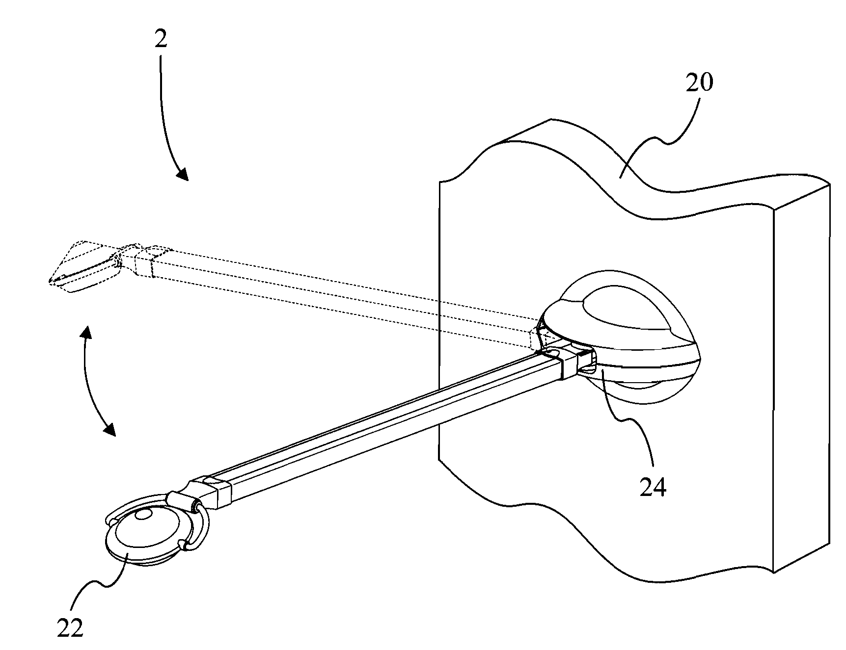
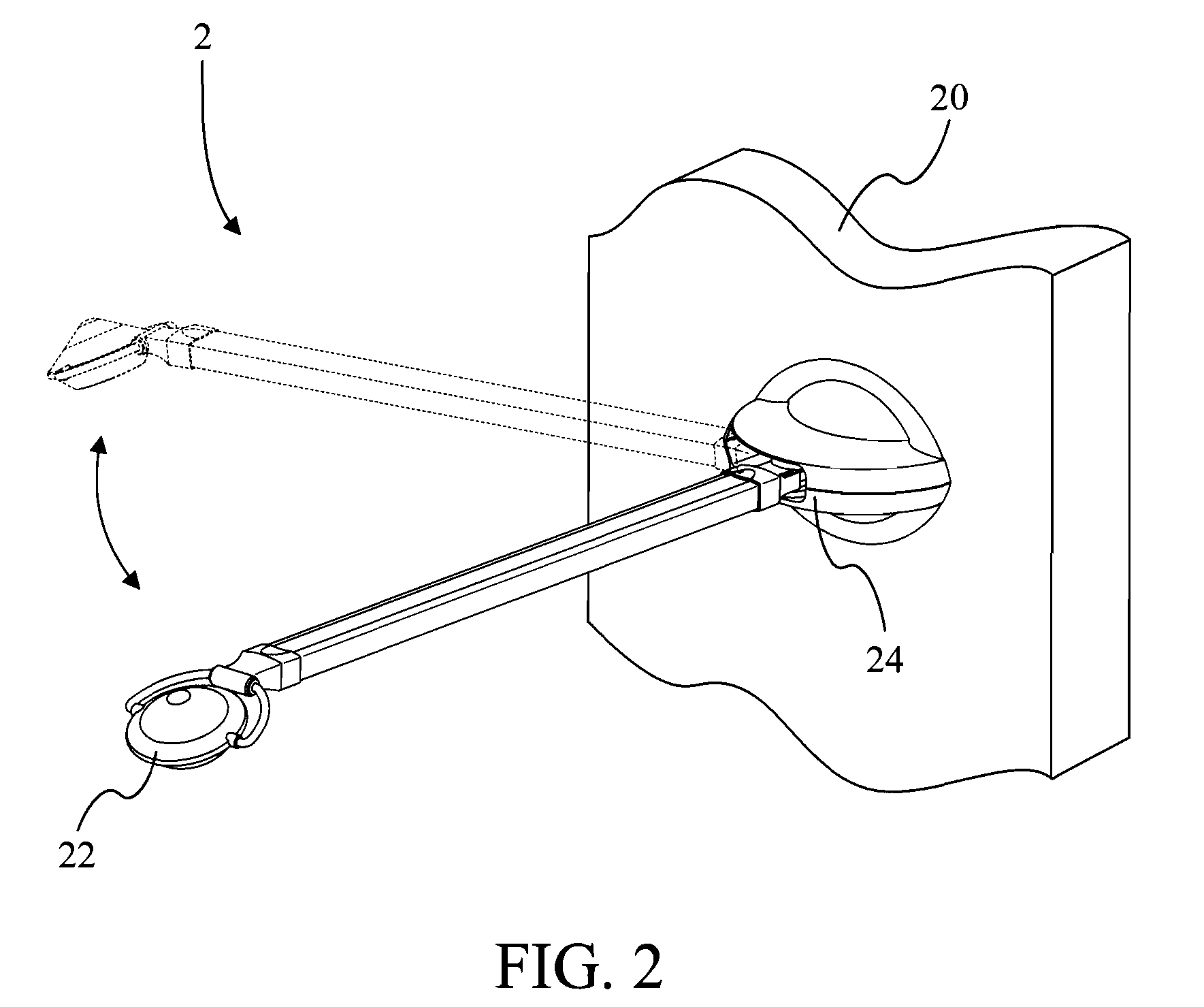
[0029]Please refer to FIG. 2. FIG. 2 is a schematic drawing of a camera apparatus 2 according to a preferred embodiment of the present invention. The camera apparatus 2 mainly contains a camera 22 as well as a support frame 24 used to support the camera 22. The support frame 24 is fixed in the wall surface 20. As shown in FIG. 2, by the locating design of the rotary joint device 242 of the present invention, the camera 22 has two localization positions related to the wall surface 20 (the dotted line is another localization position), which may serve as operation positions and restoration positions. Certainly, this invention is not limited by this embodiment and may be dependent upon the demand to provide more localization.

[0030]Please refer to FIG. 3. FIG. 3 is an exploded schematic drawing of the camera apparatus 2. The support frame 24 contains a first frame 244, a rotary joint device 242, and a second frame 246. The first frame 244 contains a bracket 2442 and a cover combined wit...


PUM


Abstract

The invention provides a rotary joint device and a support frame and a camera apparatus therewith. The rotary joint device includes a first rotary member, a second rotary member, and a positioning device. The first rotary member includes a first positioning recess space and a second positioning recess space. The second rotary member is pivotally engaged to the first rotary member and includes a hole. The positioning device includes a body, a resilient, and a positioning part. The body includes an accommodating space. The resilient is accommodated in the accommodating space and is connected to the body and the positioning part respectively. The body is disposed in the hole and is connected to the second rotary member. The positioning part is urged against the first rotary member and is accommodated in the first positioning recess space or the second positioning recess space.

Description

CROSS-REFERENCE TO RELATED APPLICATIONS[0001]This non-provisional application claims priority under 35 U.S.C. §119(a) on Patent Application No. 097209827 filed in Taiwan on Jun. 4, 2008, the entire contents of which are hereby incorporated by reference.BACKGROUND OF THE INVENTION[0002]1. Field of the Invention[0003]The present invention relates to a rotary joint device and a support frame and a camera apparatus equipped with the rotary joint device, and more particularly, to a rotary joint device with locating function, a support frame and a camera apparatus equipped with the rotary joint device.[0004]2. Description of the Prior Art[0005]At present, the hanging-type video camera or photographing on the market usually adopts two ways to adjust positions and angles of the video camera device. Moreover, the angle adjustment may be divided into the angular adjustment between the cantilever and the fixed camera thereon, and the degree rotation adjustment of the cantilever and the fixed f...

Claims


Application Information

Patent Timeline
IPC IPC(8): G03B17/56A47F5/00
CPCF16M11/08F16M11/10G03B17/56F16M13/02F16M11/2014G03B17/561
Inventor CHANG, JUNG WENLAI, CHUN FENGYAN, BO RAN
Owner QUANTA COMPUTER INC
Why Eureka
Eureka Blog
Learn More