System and Method for Locating of Distal Holes of an Intramedullary Nail

a technology of distal holes and systems, applied in the field of systems and methods of detecting the location of distal holes of intramedullary nails, can solve the problems of large radiation exposure, difficult to determine the location of distal holes, blind transverse holes, etc., and achieve the effect of precise drilling of distal holes through the bone, high accuracy and high accuracy

Inactive Publication Date: 2009-12-10
L R S ORTHO
View PDF27 Cites 33 Cited by
  • Summary
  • Abstract
  • Description
  • Claims
  • Application Information

AI Technical Summary

Benefits of technology

[0017]The system may further comprise, or may be adapted for use with, an X-ray machine, such as C-arm allowing taking X-ray images of the bone with the nail and the jig attached to it, from different angular positions. The X-ray images may provide information such as relative disposition of the alignment pin with respect to the distal hole axis and circularity of the distal holes. The C-arm may further comprise a mirror attached to its receiver or its source, which, together with the laser pointer of the alignment pin, allow a precise alignment of the C-arm's axis with the alignment pin axis and consequently the distal hole axis.
[0029]The method provides a precise alignment of the positioning head axis and the hole axis, so that when the drill bit is inserted therein after the adjustment is completed is aligned with the hole axis and precise drilling of holes through the bone may be achieved. In addition, the number of X-ray images needed to be taken is relatively small, e.g. it may be sufficient to only take from two to four images, which prevents unnecessary radiation of the patient and the medical stuff.

Problems solved by technology

The problem has always been that once the nail is inserted into the bone, the transverse holes are said to be “blind” in the terms of the bone-drilling alignment that must be achieved.
The determination of the location of the distal holes is much more difficult, due to the fact that the nail may have undergone a slight bent or twisting during the insertion thereof into the bone, so that the distal holes no longer have the same location with respect to the proximal end of the nail, as it was prior to its insertion.
Due to the above mentions limitations, majority of techniques have to rely on X-rays for assurance of the alignment.
Moreover, the technique involves a great radiation exposure of the surgeon while working with hands close to the X-ray beam.

Method used


Image

  • System and Method for Locating of Distal Holes of an Intramedullary Nail
  • System and Method for Locating of Distal Holes of an Intramedullary Nail
  • System and Method for Locating of Distal Holes of an Intramedullary Nail

Examples


Embodiment Construction

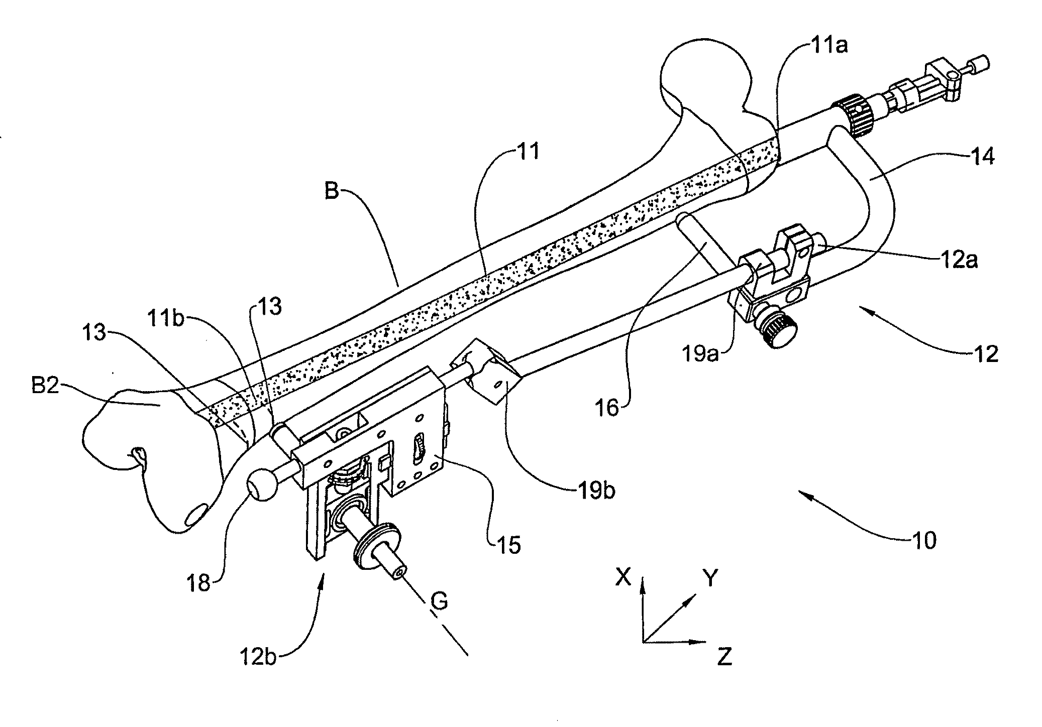
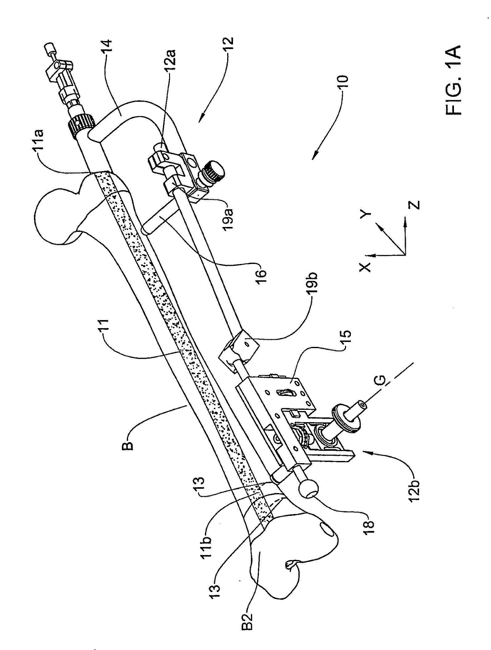
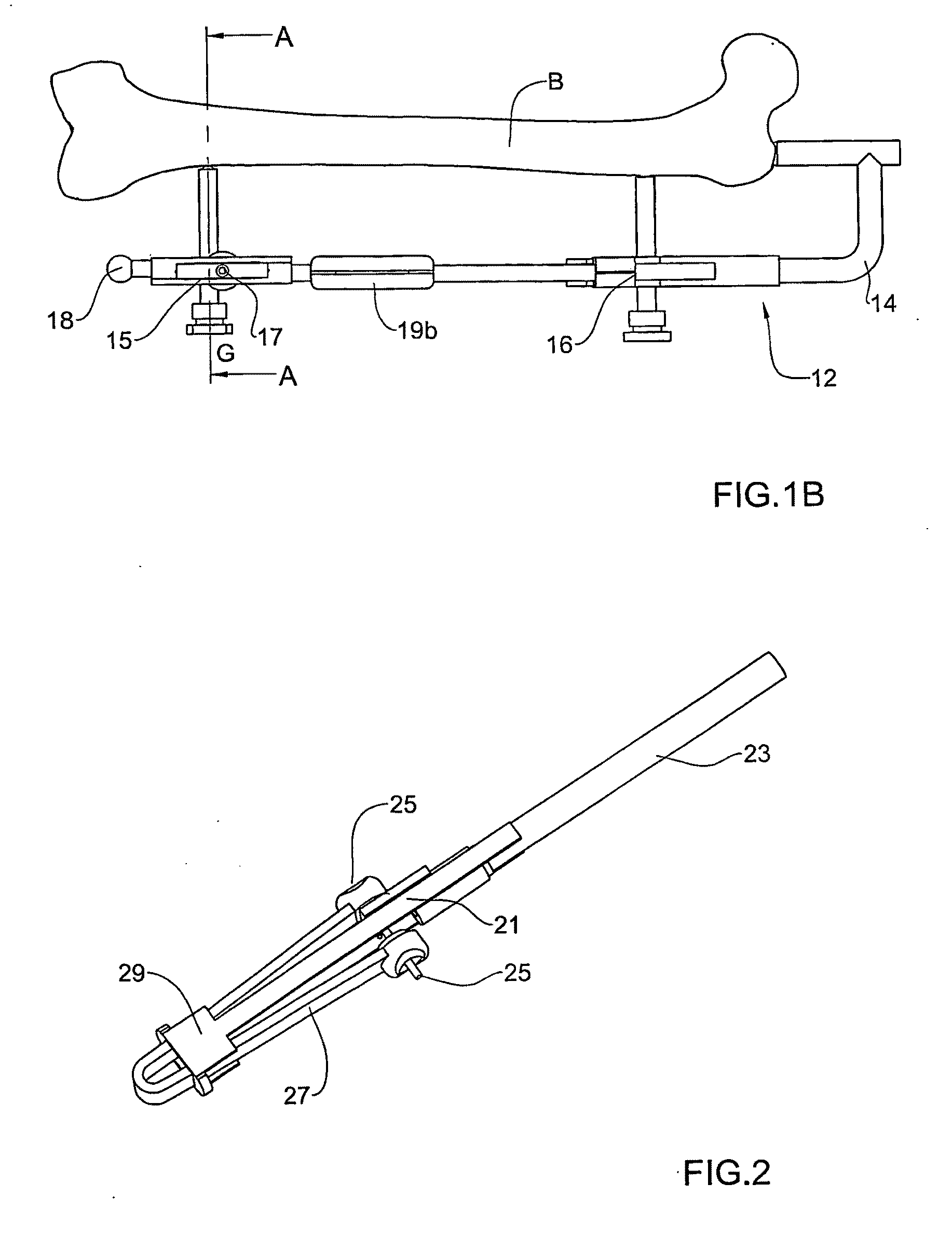
[0051]FIGS. 1A, 1B and 2 schematically illustrate a system 10 for use with a hollow intramedullary nail 11 when implanted into a intramedullary canal of a bone B. The nail has a proximal end 11a, a distal end 11b and two transverse distal holes 13 formed in the nail walls adjacent the distal end 11b, each having hole axis H (not shown), and is designed for determining the location of the holes 13.

[0052]The system 10 comprises a first member in the form of a jig 12 (FIGS. 1A and 2) adapted for use externally relative to the bone B, and a disposable member 22 (FIG. 2), adapted for insertion in the nail 11, when inserted in the bone B.

[0053]The jig 12 has a jig proximal end 12a and a jig distal end 12b, and it comprises a proximal support portion 16 and a distal support portion 18, respectively. The jig 12 is adapted to be attached at its proximal end to the proximal end 11a of the nail 11 by a handle 14, with both the proximal and distal support portions 16 and 18 being attached to th...


PUM


Abstract

Systems and methods for use with a hollow intramedullary nail having a proximal end, a distal end and at least one distal hole formed in the nail's wall adjacent said distal end and having a hole axis, for detecting a location of said distal hole when the nail is implanted into a intramedullary canal of a bone. The system includes a jig adapted for being mounted on said bone so as to constitute a bridge between the proximal end of said nail and a distal end of said bone, and having a positioning head with a guiding axis oriented generally perpendicular to the nail longitudinal axis, adapted for receiving therein at least a drill bit so that the drill bit's axis is aligned with said guiding axis, the positioning head being movable to bring said guiding axis into different spatial positions with respect to said hole axis. The system may further include at least one of the following: a disposable member insertable into said nail and having a nail light source for emitting light along said distal hole axis so as to create an illuminated spot on an outer surface of said bone, said nail light source is of a kind providing collimated light and, said member further includes means for positioning an axis of a collimated beam created by said light along said hole axis; viewing optics mountable in said positioning head along said guiding axis for viewing said illuminated spot; an alignment pin having a pin proximal end, a pin distal end, and a pin axis, and being adapted for mounting in said positioning head so that said pin axis is aligned with said guiding axis and so that the pin distal end faces towards the bone, where the pin further includes reference marks on its outer surface, visible in X-ray images.

Description

FIELD OF THE INVENTION[0001]This invention relates to systems and methods of detecting a location of distal holes of an intramedullary nail implanted into of a bone.BACKGROUND OF THE INVENTION[0002]For the surgical repair and stabilization of fractures of long bones, such as femur, tibia, humerus and fibula, it has long been known in medical practice to insert an intramedullary nail, which is a tubular metal part, of appropriate length into the interior portion of the bone. The nail usually has a pair of transverse holes adjacent to its proximal end (proximal holes) and a pair of transverse holes adjacent to its distal end (distal holes). In order to enhance the healing of the bone, the nail must provide a rigid structure about which the broken portions of the bone may adhere. Thus, the nail must be secured with respect to the bone. The securing of the nail is achieved by means of transversely extending screws or bolts which are screwed into the bone and pass through the surrounding...

Claims


Application Information

Patent Timeline
Patent Type & Authority Applications(United States)
IPC IPC(8): A61B17/58
CPCA61B17/1703A61B17/1725A61B2019/5231A61B19/5212A61B19/54A61B19/52A61B90/36A61B2090/373A61B90/361A61B90/39
Inventor LERNER, ALEXANDERNASSONOV, ALEXANDERDIAMANT, LEV
Owner L R S ORTHO
Why Eureka
Try Eureka