Generating a transition system for use with model checking

Active Publication Date: 2009-12-10
GECKO HLDG PTY LTD +2
51 Cites 48 Cited by

AI-Extracted Technical Summary

Problems solved by technology

At the same time the transformation to the XML domain does n...

Method used

[0058]The queries return node IDs, and the node ids then directly relate to the corresponding node IDs in the CFG. Each query returns the node IDs included in the XML document at which the query is matched. The corresponding position on the CFG is then easy to identify by finding the node that has the same node ID in the CFG. That node is then given a suitable label corresponding to the query. The resulting labelled CFG ...

Benefits of technology

[0017]It is an advantage of the invention that the problem of labelling a transition system can be transformed into the XML domain so that detailed information about the data can be extracted using queries in a format that can be run in the XML domain which are well known. At the same time the transformation to the XML domain does not prevent the use of efficient model checking technologies.
[0022]timing analysis of the source code.
[0023]The method may be performed as the source code is being written or during compile time.
[0024]Querying the XML representation of the data comprises running a query on the XML representation of the data and the query may check for static properties of the source code, for example, location of variable and function declarations, comparisons between variables and numbers, initialisations of varia...

Abstract

The invention concerns model program analysis of software code using model checking. Initially, a transition system (22) and an extensible markup language (XML) (24) representation of the data is generated. Next, labels (26) for the transition system are generated by querying the XML representation of the data using (markup) query language. The labels and the structure of the transition system are then used as input to model checking techniques to analyse the software code (28). It is an advantage of the invention that the problem of labelling a transition system can be transformed into the XML domain so that detailed information about the software code can be extracted using queries in a format that can be run in the XML domain which are well known. At the same time the transformation to the XML domain does not prevent the use of efficient model checking technologies.

Application Domain

Data processing applicationsHardware monitoring +4

Technology Topic

Self checkingSoftware +7

Image

  • Generating a transition system for use with model checking
  • Generating a transition system for use with model checking
  • Generating a transition system for use with model checking

Examples

  • Experimental program(1)

Example

BEST MODES OF THE INVENTION
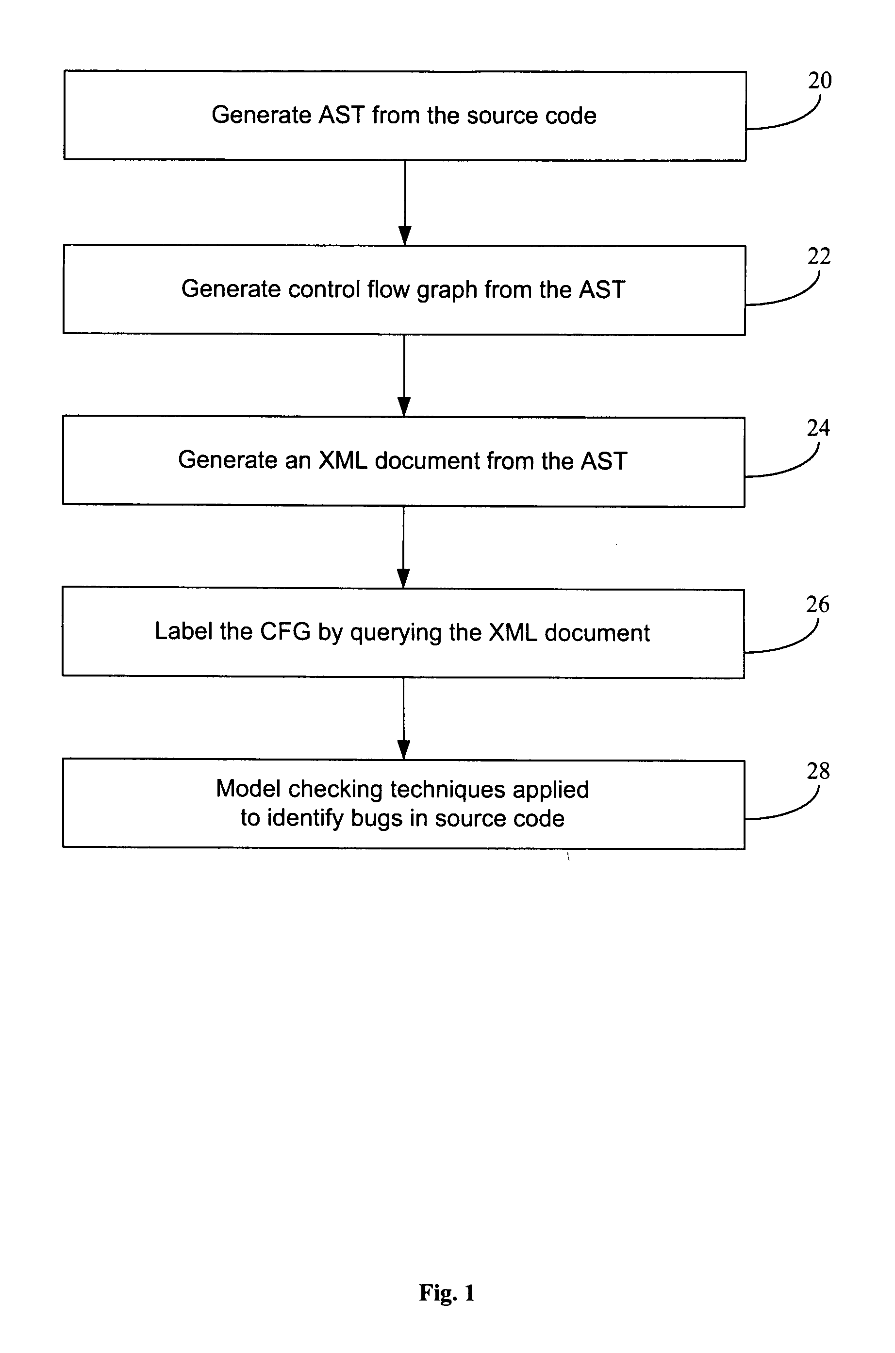
[0049]An example of using the invention to detect static software bugs in source code using model checking will now be described with reference to the flowchart of FIG. 1. We note that while this flow chart has been depicted as a flow of sequential steps, in fact some steps can be performed in parallel. For example, steps 22 and steps 24 of FIG. 1 can be performed in parallel.
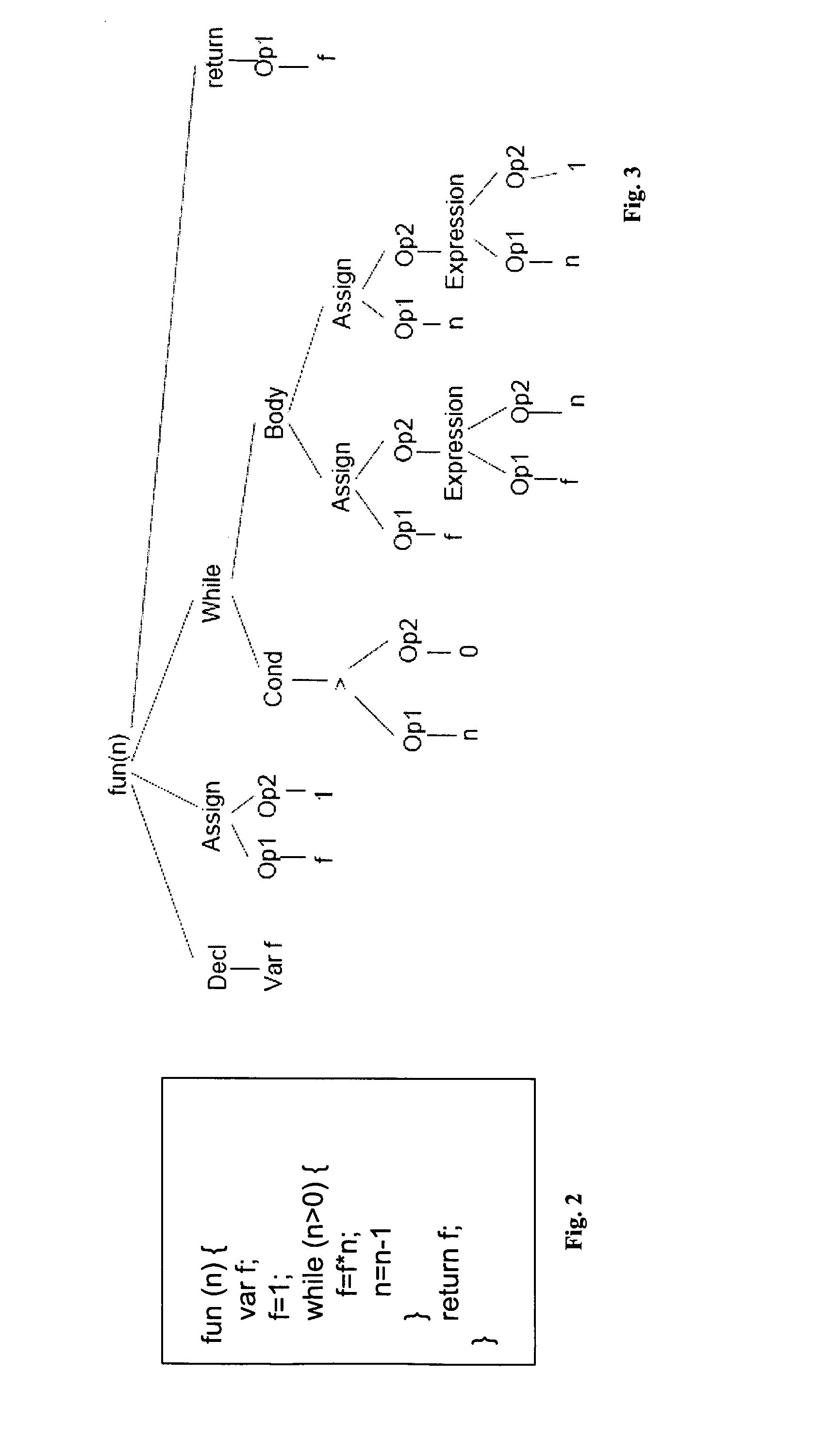
[0050]Take the source code of the sample program shown in FIG. 2. This sample program is automatically converted 20 to an abstract syntax tree (AST) shown in FIG. 3. An AST is a labelled tree, where the nodes are labelled by operators of a program, and where the leaf nodes represent its operands (i.e., variables or constants). The AST is an intermediate structure generated when parsing (i.e., reading in) a program and it is a natural precursor to the control flow graph (CFG). Every node in the AST has a unique identifier called a node ID (not shown).
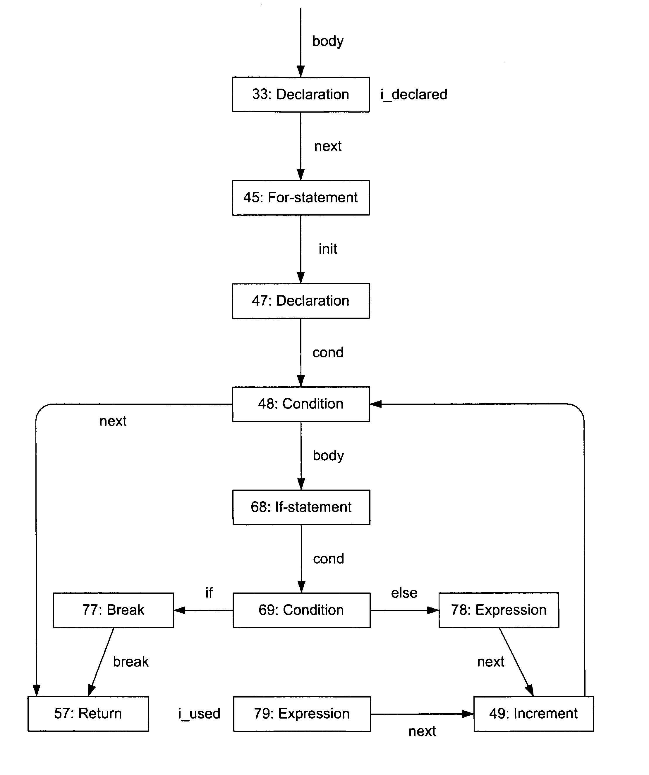
[0051]Next, we automatically generate 22 a CFG as shown in FIG. 4. In this example from the AST. Information from the AST is translated to the CFG format, including node IDs. The aim now is to label (annotate) the CFG so that we can apply model checking techniques to detect software bugs in the original source code. To do this we also generate 24 an XML document from the AST as shown in FIG. 5. The XML document (FIG. 5) is a direct translation of the AST. In this way the XML document also has all the same information as the AST of FIG. 2. Again this includes the node IDs. In this XML document the node IDs are flagged by the markers including the term “id”.
[0052]Next we label 26 the CFG so that we can apply model checking techniques. We identify locations in the CFG by querying the XML document version of the source code using temporal logic. Pattern matching is the act of checking for the presence of a given pattern (in our case tree structures) in a larger structure (in our case the AST). Tree structures are very powerful and allow the definition of complex patterns. The approach is based on pattern matching program constructs on the abstract syntax tree.
[0053]The core of the invention is to use tree pattern matching algorithms and query languages from a different domain: XML document processing. In this embodiment, we use XPath as a query language to identify our labels. XPath (XML Path Language) is a terse (non-XML) syntax for addressing portions of an XML document and allows the specification of tree patterns in a very convenient way. There are also freely available (LGPL) efficient implementations available that can be used.
[0054]FIG. 6 shows two pseudo queries that could be applied to the XML representation of the source code to identify tree patterns. The first query locates instances in which a variable “f” is defined. The representation of this query in XPath syntax would appear as follows: [0055] //Decl/Var[@name=‘f’]
[0056]The second query finds locations where the variable “f” is used in the code. A representation of a simplified version of this query, which matches the code in FIG. 5 in the XPath syntax would (simplified) read as follows: [0057] //Compare //compare/*[@name=‘f’]]|//Assign/Op2/*[@name=‘f’]
[0058]The queries return node IDs, and the node ids then directly relate to the corresponding node IDs in the CFG. Each query returns the node IDs included in the XML document at which the query is matched. The corresponding position on the CFG is then easy to identify by finding the node that has the same node ID in the CFG. That node is then given a suitable label corresponding to the query. The resulting labelled CFG is shown in FIG. 7.
[0059]Since the CFG is now labelled, known model checking techniques can be applied 28 to the CFG to perform program analysis such as the identification of software bugs.
[0060]A further example will now be described. In FIG. 8 we see an XML representation of parts of an AST. The respective XPath query to find (match) the nodes where variable i is declared is constructed as shown in FIG. 9.
[0061]This XPath query now defines which nodes in the CFG should be labelled with i_declared. When applied to the XML fragment in FIG. 8, the node with cfgid “33” should be labeled, whereas the node with cfgid “47” should not. The node in the CFG that has this identifier “33” and a label is associated accordingly.
[0062]As described above converting the source code to an annotated model, given a set of properties, is done in a number of stages (steps 20 to 28). Parsing the source code yields an AST, which is prerequisite to build the CFG. The static analysis properties define atomic propositions, using XPath queries on the XML representation of the parse tree, to determine which nodes have to be annotated. The XML representation of the AST and the queries together are used by the XPath engine, to determine which atomic propositions are valid in what states. This information, together with the structure of the CFG are the building blocks of the model checking input.
[0063]The general architecture of the code and property input model conversion using the invention is shown in FIG. 10.
[0064]To optimise the method, there is no need to generate the XML document that represents the AST, but instead build the corresponding data structures that can directly be used by the XPath library that is used to perform the queries. With this optimisation, the full XML documents do not need to be generated in one step, and in the next step the XPath library has to parse these files again. By going directly to the XPath structures overhead is saved. This modification is depicted in FIG. 10 as grey link between AST and XPath.
[0065]The invention may be provided as software. When the software is installed on a computer system it is able to operate the computer system to perform the method described above. The computer includes an output device, such as a monitor, to present a user interface to the user. Using the interface the user can run their own XPath queries and construct their own properties (queries). The computer system may include storage means to store a library of queries. Parts of the method can be performed as the user is writing the source code. Alternatively, the method may be performed during compile time.
[0066]The invention may use query libraries, such as Frisch's XPath library [Fri00] for OCaml, to query its internal XML data structures for patterns of interest. Both XML and XPath are well standardised languages. Using such standards enables the invention to be used with software libraries that integrate into OCaml and offer an interface to execute XPath queries on XML data.
[0067]The invention can be applied to a range of programming languages of the source code, including C and C++. Besides other imperative programming languages that are similar to C and C++, like Java, the technology can also be applied to assembly language programs. In the case of assembly languages the queries may be less powerful on degenerated ASTs resulting from low-level assembly programs.
[0068]Quantitative Model Checking is concerned with checking for optimal behaviour. Rather than annotating states with atomic propositions, the model is annotated with weights on states and transitions. The technology described in this document can also be used to generate weights for quantitative model checking.
[0069]Once a bug is tested using the invention, the invention can be used to also give explanations why they occur and how they can be fixed. For example, a detailed explanation that not only highlights the error, but also pinpoints its location including a potential execution path that leads to this error. This would be a valuable assistance to the user in increasing software development productivity.
[0070]It will be appreciated by persons skilled in the art that numerous variations and/or modifications may be made to the invention as shown in the specific embodiments without departing from the spirit or scope of the invention as broadly described. For instance, some of the steps shown in FIG. 1 could be carried out in parallel rather than sequentially, as shown.
[0071]For example, as part of program analysis the method could be used for finding defects in programs, finding security vulnerabilities, generic program analysis (i.e. computing metrics about programs) and timing analysis (i.e. making statements about a program's worst case execution times or for optimisation).
[0072]The present embodiments are, therefore, to be considered in all respects as illustrative and not restrictive.
REFERENCES
[0073] [APMV04] G. Antoniol, M. Di Penta, G. Masone, and U. Villano. Compiler Hacking for Source Code Analysis. Software Quality Journal, 12:383-406, 2004. [0074] [AS] Calculating the Total Cost of Development. http://wp.bitpipe.com/resource/org—1039183786—34/CTCD_WP—0902_bpx.pdf. [0075] [Fri00] Alain Frisch. XPath Library for OCaml. http://www.eleves.ens.fr/home/frisch/soft.html#xpath, 2000.
[0076][SS98] D. Schmidt and B. Steffen. Program Analysis as Model Checking of Abstract Interpretations. In Proc. of Static Analysis Symposium (SAS'98), Pisa, Italy, 1998.

PUM

no PUM

Description & Claims & Application Information

We can also present the details of the Description, Claims and Application information to help users get a comprehensive understanding of the technical details of the patent, such as background art, summary of invention, brief description of drawings, description of embodiments, and other original content. On the other hand, users can also determine the specific scope of protection of the technology through the list of claims; as well as understand the changes in the life cycle of the technology with the presentation of the patent timeline. Login to view more.
Why Eureka
Try Eureka