
Hydrodynamic coupling

Inactive Publication Date: 2009-12-17
VOITH PATENT GMBH
View PDF18 Cites 7 Cited by
  • Summary
  • Abstract
  • Description
  • Claims
  • Application Information

AI Technical Summary

Benefits of technology

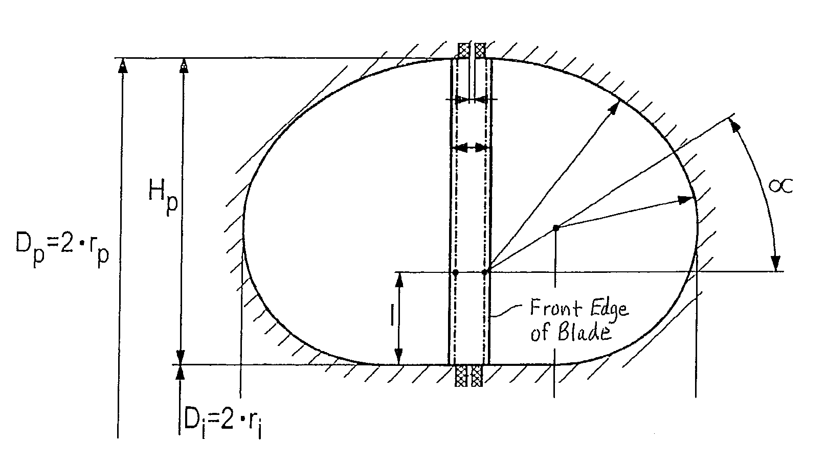
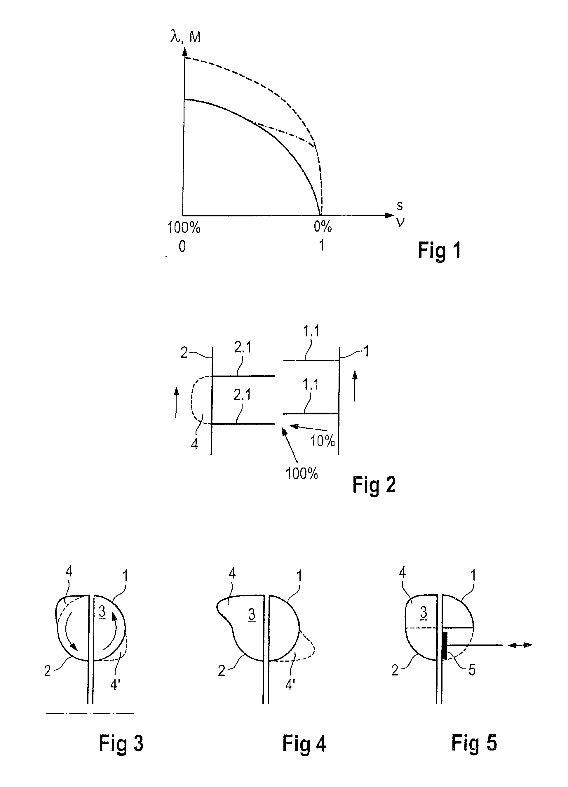
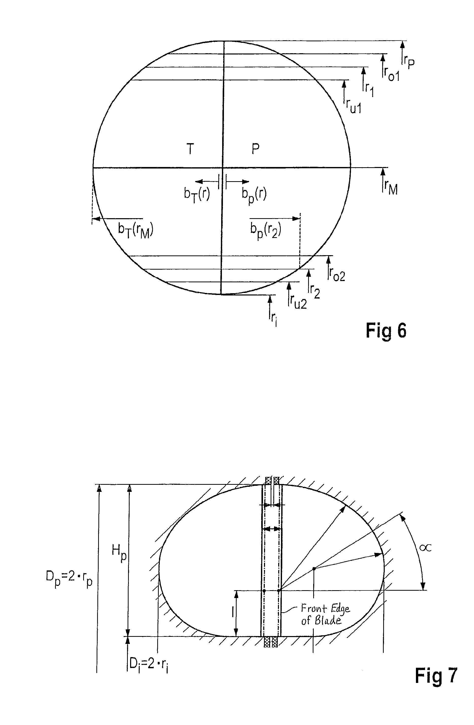
[0019]This inventively provided convexity has the following effect: When the working medium flows out of the impeller into the turbine wheel, as described its flow direction is essentially parallel to the coupling rotational axis, at least viewed in axial section through the hydrodynamic coupling. The working medium, which leaves the impeller in the radially outer area of the impeller, thus flows toward and into the convexity. Due to the circumferential component that also now comes into play in the working medium flow from the impeller into the turbine wheel, however, a work medium flow essentially directed into the convexity does not occur in every operating condition relative to the circumferential direction of the hydrodynamic coupling and thus circularly about the rotational axis of the hydrodynamic coupling. On the contrary, there are certain operating conditions, specifically at a high slip between impeller and turbine wheel, in which the circumferential components of the working medium flow features the flow being more strongly directed in the circumferential direction of the hydrodynamic coupling than in the axial direction of the hydrodynamic coupling. In these operating conditions, the working medium flows directly into the convexity only to a limited extent or the working medium essentially does not flow or does not flow directly into the convexity. In contrast, at low slip the working medium flow is directed less in the circumferential direction and is thus more strongly directed in the axial direction, and direct flow into the convexity is more pronounced in comparison.
[0031]Another advantage of the inventive method is that a correspondingly embodied hydrodynamic coupling has relatively low no-load losses because even the air that is in the working chamber and is discharged by the working medium is carried into the inventively provided convexity that differs from the basic course of the working chamber and is swirled around, and thus the undesired torque transmission is reduced or suppressed.

Problems solved by technology

However, a high torque progression or λ progression for a hydrodynamic coupling can lead to the hydrodynamic coupling causing the engine to stall when there is high slip, for instance at 100 percent slip, during acceleration of the vehicle from zero or a slow engine speed because the torque transmitted by the hydrodynamic coupling and against which the engine is working is too great.
However, this progression depicted with the dashed line could lead to the drive engine stalling in a high slip range.

Method used


Image

  • Hydrodynamic coupling
  • Hydrodynamic coupling
  • Hydrodynamic coupling

Examples


Embodiment Construction

[0041]Referring now to the drawings, and more particularly to FIG. 1, FIG. 1 was already explained above. With the inventive hydrodynamic coupling, it is possible to attain a λ progression or torque progression over slip or speed ratio, beginning at 100 percent slip, initially along the solid line, then along the dot-dash line, and finally along the dashed line. In the past only the progression along the solid line or along the dashed line was possible.

[0042]FIG. 2 depicts the axial component and the circumferential component of the working medium flow from impeller 1 into turbine wheel 2 at 10% slip and at 100% slip. The dashed line indicates the convexity 4 in the turbine wheel. The impeller blades and turbine blades for impeller 1 and turbine wheel 2 are indicated with 1.1 and 2.1 respectively. The two perpendicular arrows on the left and right in FIG. 2 indicate the direction of rotation for impeller 1 and turbine wheel 2.

[0043]This figure depicts in particular the effect of the...


PUM


Abstract

A hydrodynamic coupling has an impeller and a turbine wheel that together form a toroidal working chamber. Viewed as an axial section through the hydrodynamic coupling the working chamber has a circular or essentially circular cross-section with a convexity in the axial direction on the circumference in the radially outer area of said turbine wheel and / or in the radially inner area of said impeller.

Description

CROSS REFERENCE TO RELATED APPLICATIONS[0001]This is a continuation of PCT application No. PCT / EP2007 / 010502, entitled “HYDRODYNAMIC COUPLING”, filed Dec. 4, 2007, which is incorporated herein by reference.BACKGROUND OF THE INVENTION[0002]1. Field of the Invention[0003]The invention relates to a hydrodynamic coupling, that is a turbo-engine, that works according to the Föttinger principle in order to transmit drive power hydrodynamically and thus wear-free[0004]2. Description of the Related Art[0005]Hydrodynamic couplings have been known for decades. They have an impeller and a turbine wheel that form a toroidal working chamber that is filled with or can be filled with working medium. One skilled in the art distinguishes between constant filling couplings and flow-through couplings. In constant filling couplings, the working medium is always disposed within the hydrodynamic coupling. In flow-through hydrodynamic couplings, an external working medium cycle is connected to the couplin...

Claims


Application Information

Patent Timeline
IPC IPC(8): F16D33/18
CPCF16D33/06F16D57/005F16D33/20
Inventor SCHIPS, RAINER
Owner VOITH PATENT GMBH
Learn More