Method for Manufacturing Tube and Fin Heat Exchanger with Reduced Tube Diameter and Optimized Fin Produced Thereby

a technology of heat exchanger and tube, which is applied in the direction tubular elements, stationary conduit assemblies, etc., can solve the problems of limited commercial success of small diameter coils, prohibit commercially viable manufacturing of any but the shortest heat exchangers, and difficult lacing process, so as to increase the stiffness and rigidity of heat exchanger fins, increase the tendency to maintain proper alignment, and increase the effect of fin stiffness

Inactive Publication Date: 2009-12-17
GOODMAN GLOBAL INC
View PDF71 Cites 35 Cited by
  • Summary
  • Abstract
  • Description
  • Claims
  • Application Information

AI Technical Summary

Benefits of technology

[0015]The objects above as well as other features of the invention are realized in an improved method for manufacturing tube and fin heat exchangers that, according to a preferred embodiment, includes a process for increasing the stiffness and rigidity of heat exchanger fins. Stiffer fins have a greater tendency to maintain proper alignment within a stack of fins, which aids in lacing long stacks of fins with small (e.g., 5 mm) diameter tubing. Preferably, fin stiffness is increased by forming a plurality of longitudinal ribs within the fin during the fin stamping process. More preferably still, two ribs for each longitudinal row of collared holes are provided.
[0016]The preferred embodiment of the invention also includes a slotted heat exchanger fin that is dimensioned and arranged for optimized thermodynamic performance when used with small diameter tubing, thus reducing the space required for a given heat exchanger system.
[0017]The fin preferably includes slits with ends having a 30 degree incident angle with respect to the airflow, which helps to re-direct the airflow from the tube passing through the collared hole to avoid the wake region behind the tube and provides for a more effective air mixture in parallel slits. The angled slit ends also create turbulence at the area of the fin that has largest distance to neighboring tubes, which enhances the heat transfer over that area.

Problems solved by technology

Although the industry desires to manufacture heat exchanger coils of smaller diameter, manufacturing techniques of prior art have restricted such coils to short lengths, with the result that small diameter coils have had limited commercial success.
The source of the problem is that when the hairpin tubing becomes too small, the lacing process becomes exceedingly difficult, prohibiting commercially viable manufacturing of any but the shortest heat exchangers.
However, when 5 mm copper tubing is used, it has not been commercially feasible to lace a heat exchanger longer than about 36 inches because of the “Chinese handcuff” effect of the large number of fins.
Fins of these prior art fin dimensions do not deliver optimized performance for smaller diameter, e.g., 5 mm, tubes.

Method used


Image

  • Method for Manufacturing Tube and Fin Heat Exchanger with Reduced Tube Diameter and Optimized Fin Produced Thereby
  • Method for Manufacturing Tube and Fin Heat Exchanger with Reduced Tube Diameter and Optimized Fin Produced Thereby
  • Method for Manufacturing Tube and Fin Heat Exchanger with Reduced Tube Diameter and Optimized Fin Produced Thereby

Examples


Embodiment Construction

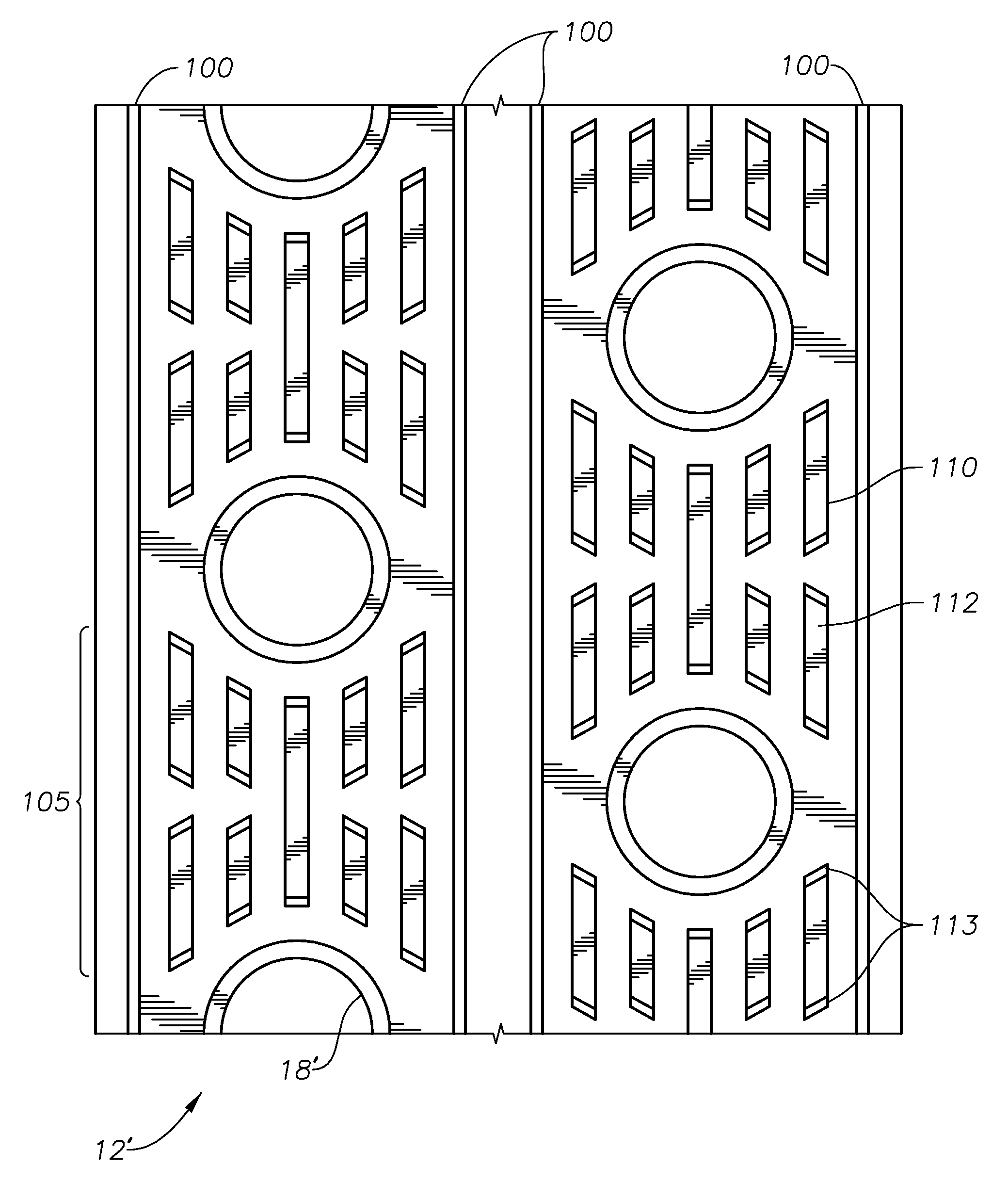
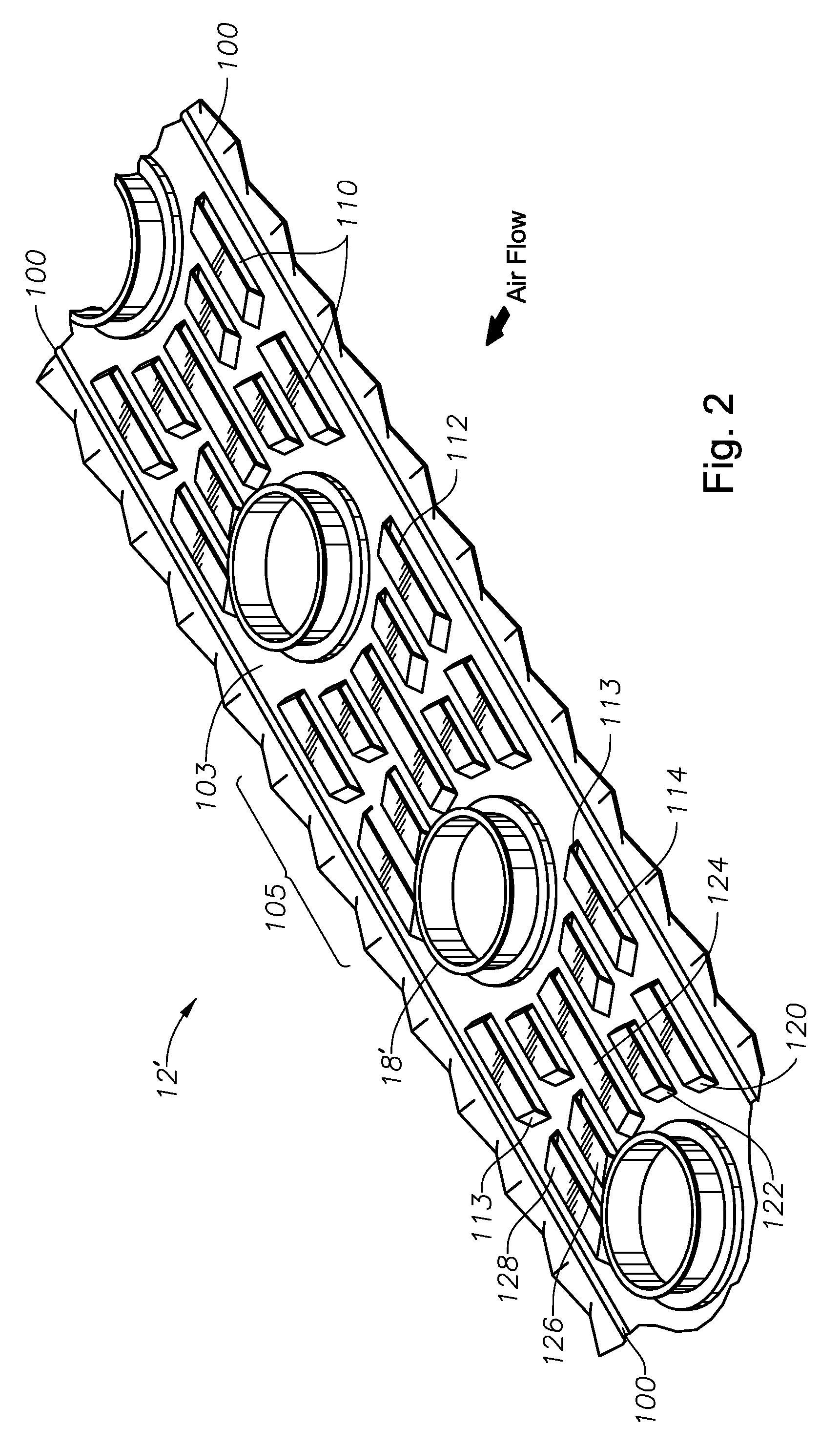
[0030]FIGS. 2-12 illustrate a fin 12′ dimensioned for small tubing, e.g. 5 mm outer diameter or less, optimized for use with a condenser or evaporator of a conventional air conditioner. FIGS. 2 and 3 illustrate a heat exchanger fin 12′ according to a first embodiment of the invention that is characterized by a single longitudinal row of collared holes 18′ for use in a single-row coil assembly. FIGS. 4-8 illustrate a heat exchanger fin 12′ according to a second embodiment of the invention that contains two longitudinal rows of collared holes 18′ for use in a double-row coil assembly. However, fins 12′ may be arranged for three, four, five, and six or more rows of coils according to the invention. The leading and trailing edges of fin 12′ preferably have corrugated edges.

[0031]Referring primarily to FIGS. 2-6, according to the preferred embodiment of the invention, a 5 mm or smaller tube and fin heat exchanger manufacturing process includes a novel and unobvious processing step in for...


PUM


Abstract

An improved method for manufacturing tube and fin heat exchangers that, according to a preferred embodiment, includes a process for increasing the stiffness and rigidity of heat exchanger fins. Stiffer fins have a greater tendency to maintain proper alignment within a stack of fins, which aids in lacing long stacks of fins with small (e.g., 5 mm) diameter tubing. Preferably, fin stiffness is increased by forming a plurality of longitudinal ribs within the fin during the fin stamping process. More preferably still, two ribs for each longitudinal row of collared holes are provided. The preferred embodiment also includes a slotted heat exchanger fin that is dimensioned and arranged for optimized thermodynamic performance when used with small diameter tubing, thus reducing the space required for a given heat exchanger system.

Description

CROSS REFERENCE TO RELATED APPLICATION[0001]This application is based upon provisional application 61 / 061,498 filed on Jun. 13, 2008, the priority of which is claimed.BACKGROUND OF THE INVENTION[0002]1. Field of the Invention[0003]This invention relates generally to tube and fin heat exchangers, and in particular, to a novel fin design for tube and fin heat exchangers.[0004]2. Description of the Prior Art[0005]As illustrated in FIG. 1, a typical tube and fin heat exchanger (10) consists of a stack of generally planar metallic fins (12) sandwiched between a top end plate (14) and a bottom end plate (16). The terms “top” and “bottom” used for designating heat exchanger end plates are derived based on the heat exchanger orientation during expansion in a vertical hairpin expander press and are not necessarily indicative of the heat exchanger orientation in any particular installation.[0006]The fins (12) have a number of collared holes (18) formed therethrough, and the top and bottom end...

Claims


Application Information

Patent Timeline
Patent Type & Authority Applications(United States)
IPC IPC(8): F28F7/00F28D1/04
CPCF28D1/0475F28F2215/10F28F1/325F28F1/32F28D1/04F28F1/10F28F1/22
Inventor CHEN, PEI PEITHARP, RUSSELL
Owner GOODMAN GLOBAL INC
Why Eureka
Try Eureka