Wave energy converter

a technology of wave energy and converter, which is applied in the direction of water-power plants, machines/engines, electric generator control, etc., can solve the problems of destroying many prior art land- or shore-based systems, unable to meet the requirements of the unit that is sufficiently robust to withstand the enormous, and unable to meet the requirements of the unit, etc., to achieve the effect of increasing the braking action, improving the braking effect, and optimising the amount of usable energy generated

Inactive Publication Date: 2009-12-17
PROTEAN ENERGY AUSTRALIA
View PDF14 Cites 46 Cited by
  • Summary
  • Abstract
  • Description
  • Claims
  • Application Information

AI Technical Summary

Benefits of technology

[0014]In another embodiment said submerged member and buoyant means are adapted to have substantially positive buoyancy in use, and said mooring means comprises a braking system for applying a braking action to the support structure via the mooring means. Preferably said braking system is adapted to increase the braking action when the energy extracted by the energy extraction means i...

Problems solved by technology

Although there has been a desire to harness the energy of waves for hundreds of years, past attempts have met with limited success.
One of the major difficulties in the past has been to design a unit that is sufficiently robust to withstand the enormous power that is possessed by the ocean's waves.
In storm conditions the wave e...

Method used


Image

  • Wave energy converter
  • Wave energy converter
  • Wave energy converter

Examples


first embodiment

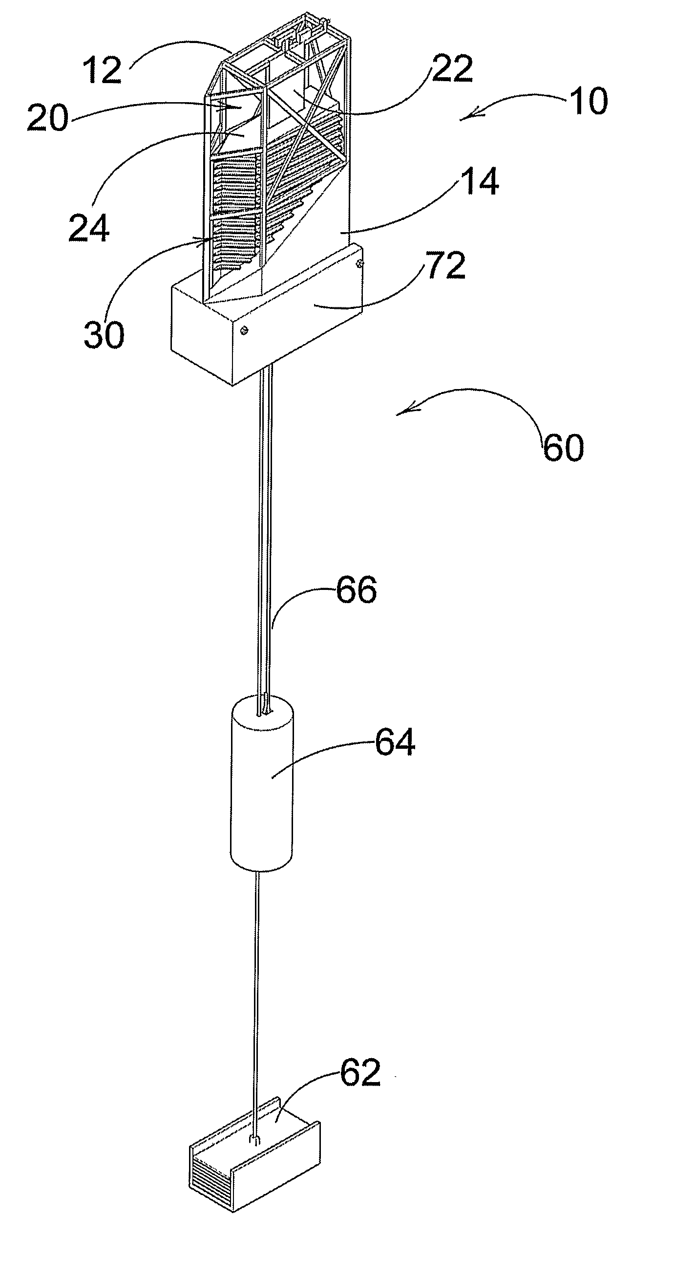
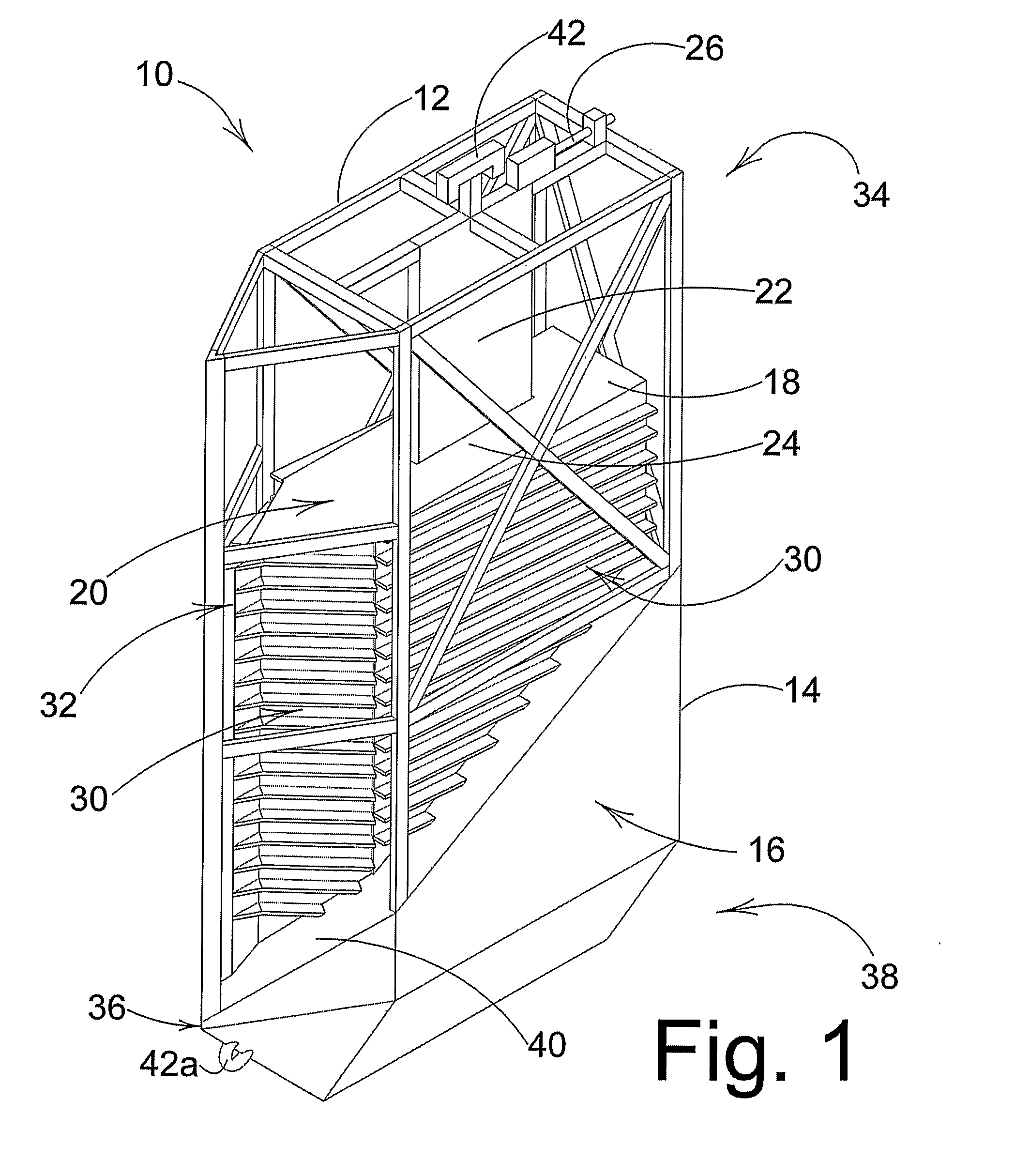
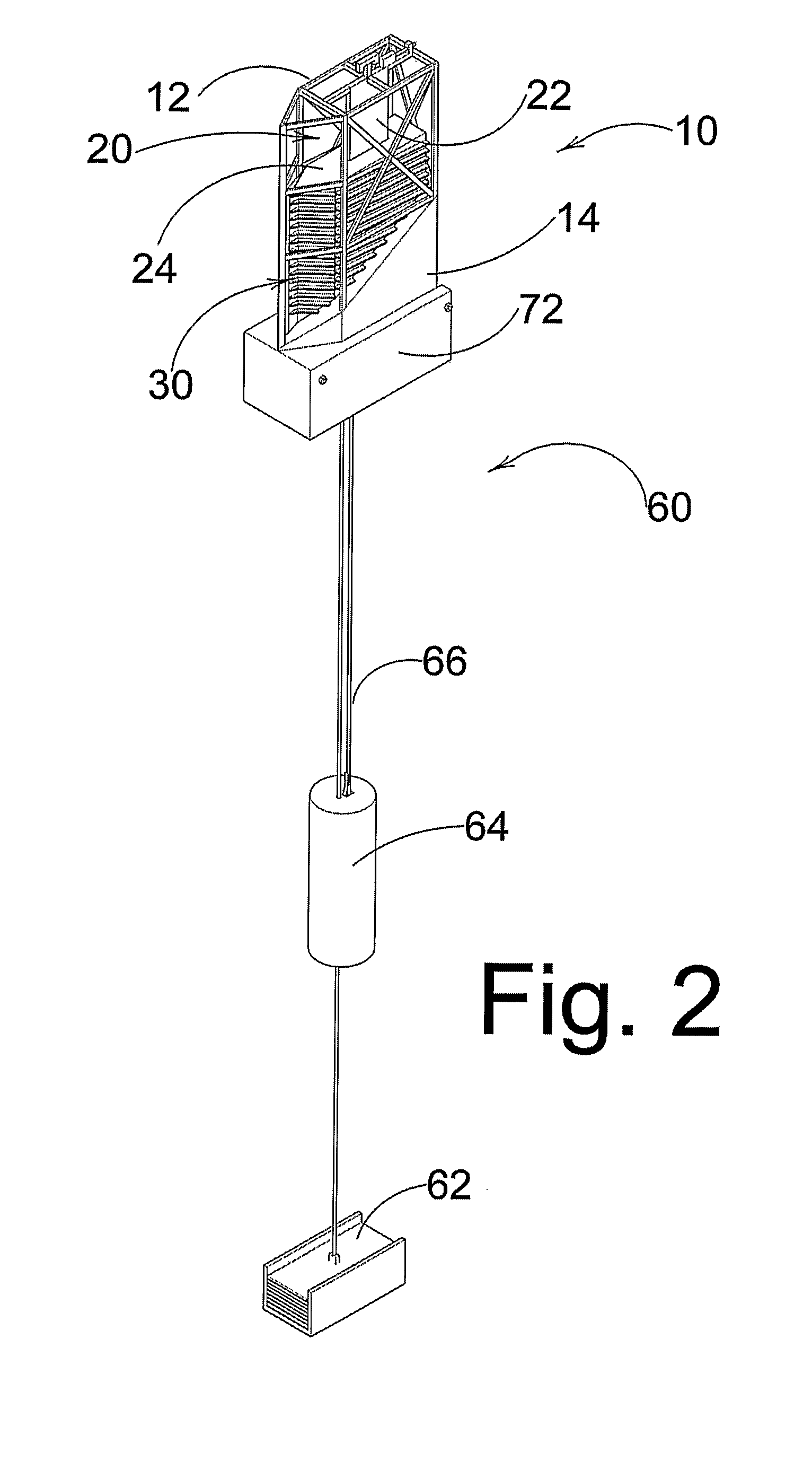
[0042]the wave energy converting apparatus 10 of the present invention, as illustrated in FIGS. 1 to 7 of the accompanying drawings, comprises an elongate support structure 12 designed to extend above a mean water level in the ocean. The apparatus 10 uses surging, heaving, buoyancy and hydrodynamic forces to extend the theoretical maximum energy extraction from 50% for a single heaving body to 100%. The support structure 12 is in the form of a frame having a submerged member 14 provided in connection therewith below the mean water level. The support structure 12 is also provided with a buoyant means to enable the support structure to float in the ocean in a generally upright orientation. In the illustrated embodiment the buoyant means is in the form of a buoyancy tank 16 provided within the submerged member 14, as will be described in more detail below. In this embodiment the buoyancy tank 16 is normally filled with sufficient air to give the submerged member 14 an overall positive ...

second embodiment

[0063]FIGS. 8 to 11 illustrate a wave energy converting apparatus 44 and its associated tension mooring system 50 in accordance with the invention. The wave energy converting apparatus 44 comprises an elongate support structure 45 designed to extend above a mean water level in the ocean. The support structure 45 is in the form of a vertically oriented column having a submerged member 46 provided in connection therewith below the mean water level. The support structure 45 of this embodiment is also provided with a buoyant means to enable the support structure to float in the ocean in a generally upright orientation. In the illustrated embodiment the buoyant means is in the form of a buoyancy tank 47 (not visible) provided within the submerged member 46. As with the previous embodiment, the buoyancy tank 47 is normally filled with sufficient air to give the submerged member 46 an overall positive buoyancy.

[0064]The apparatus 44 further comprises a float member 48 of positive buoyancy ...


PUM


Abstract

A wave energy converting apparatus 44 and its associated tension mooring system 50 is described. The wave energy converting apparatus 44 comprises an elongate support structure 45 designed to extend above a mean water level in the ocean. The support structure 45 has a submerged member 46 provided in connection therewith below the mean water level. A float member 48 of positive buoyancy is slidably mounted on the support structure 45 so as to be movable in a vertical direction. The apparatus 44 also comprises a linear electric generator 49 having a stator provided in connection with the support structure 45 and a translator integrated into the body of the float member 48. Differential motion of the float member 48 relative to the support structure 45 results in the generation of electrical power by the linear electric generator 49. The tension mooring system 50 comprises a cable 51 extending from a ballast means 52 to a counterbalancing means 53 adapted to be suspended from the submerged member 46 via a pulley mechanism 54. The tension mooring system 50 allows the apparatus 44 to be “tuned” to the prevailing ocean conditions.

Description

FIELD OF THE INVENTION[0001]The present invention relates to wave energy converters for converting ocean wave energy into electrical energy and relates particularly, though not exclusively, to such wave energy converters that operate on the principles of buoyancy, hydrodynamic pressures, and oscillation. The invention relates more particularly to a tension mooring system for a wave energy converter.BACKGROUND TO THE INVENTION[0002]At the beginning of the third millennium the concern of people everywhere is increasingly on sustainability. As people realise that fossil fuels are a finite energy resource, the search for renewable, clean energy sources has become more urgent. Global warming and climate change have focussed attention on the need to reduce our dependence on fossil fuels. One of the most promising renewable energy sources is wave energy. It has been estimated that the worldwide energy potential of wave power is 2 Terawatts, which is equivalent to a worldwide resource of ab...

Claims


Application Information

Patent Timeline
IPC IPC(8): F03B13/18B63B21/00
CPCB63B35/44B63B2035/4466E02B9/08Y02E10/38F05B2210/18F05B2220/707F05B2240/917F03B13/1845Y02E10/30
Inventor MOORE, SEAN DEREK
Owner PROTEAN ENERGY AUSTRALIA
Why Eureka
Try Eureka