Battery-charging method and battery-charging apparatus

a battery and battery technology, applied in the field of battery charging methods and apparatuses, can solve the problems of increasing the size of the electronic packaging substrate, increasing the number of components, etc., and achieve the effect of improving battery charging efficiency

Inactive Publication Date: 2009-12-17
MAZDA MOTOR CORP
View PDF8 Cites 50 Cited by
  • Summary
  • Abstract
  • Description
  • Claims
  • Application Information

AI Technical Summary

Benefits of technology

[0011]This makes it possible to charge the battery using the external power source without increasing the number of components only for charging of the battery, and effectively improve battery charging efficiency based on the use of the diode rectifier.

Problems solved by technology

However, an approach of providing a diode rectifier in a power supply system only for charging to a battery involves a problem about undesirable effects on layout, because it leads to increase in the number of components and consequently to increase in size of an electronic packaging substrate.

Method used


Image

  • Battery-charging method and battery-charging apparatus
  • Battery-charging method and battery-charging apparatus
  • Battery-charging method and battery-charging apparatus

Examples


first embodiment

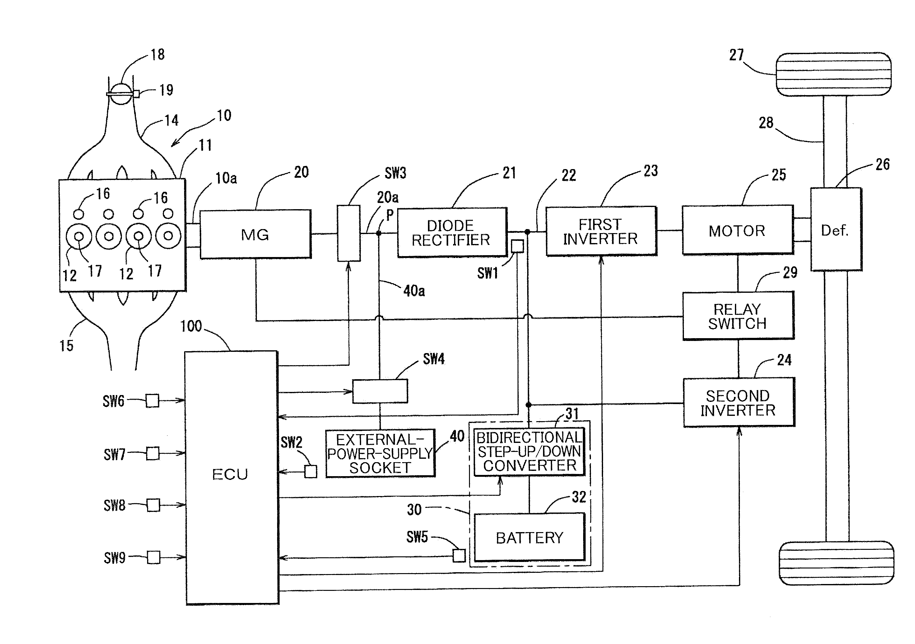
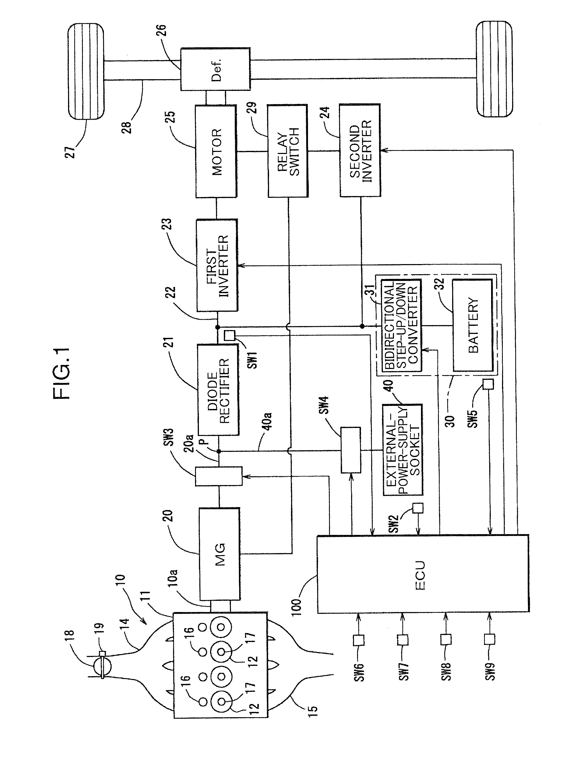
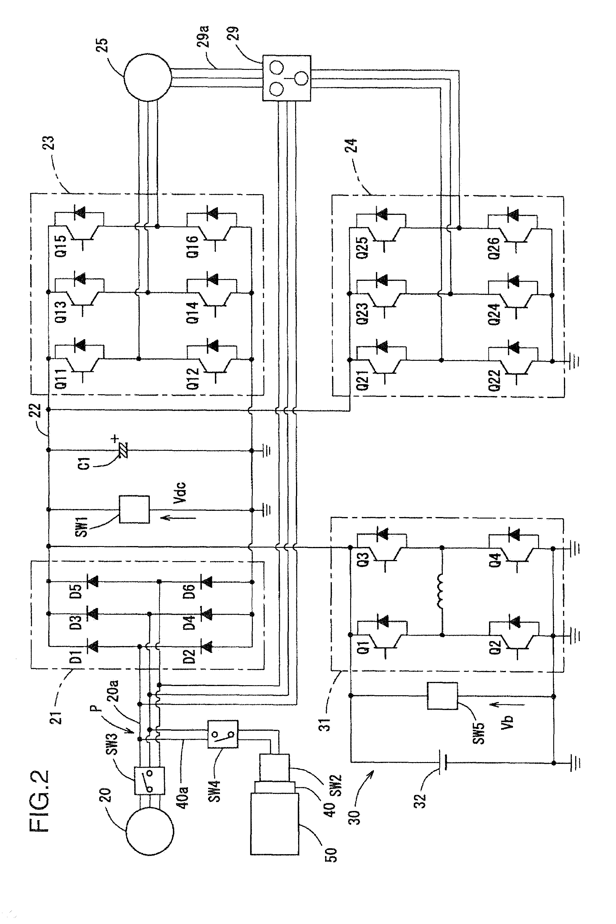
[0025]With reference to FIGS. 1 to 6, a first embodiment of the present invention will be described. FIG. 1 is a schematic block diagram showing a hybrid vehicle equipped with a battery-charging system according to the first embodiment, and FIG. 2 is a schematic diagram showing an electric circuit of the battery-charging system. As shown in FIG. 2, the hybrid vehicle in the first embodiment is a series hybrid vehicle comprising an engine 10, and a motor / generator 20 adapted to be driven by the engine 10.

[0026]The series hybrid vehicle means a vehicle designed such that a generator is driven by an engine to supply electric power to a motor therefrom, and a driving wheels are driven by the motor, as disclosed, for example, JP 2005-204370A. Differently from a parallel hybrid vehicle, in the series hybrid vehicle, the engine is used solely for generating electric power, and a driving force generated by an engine is not mechanically transferred to driving wheels.

[0027]For example, the en...

second embodiment

[0085]In the first embodiment illustrated in FIGS. 1 to 6, the first and second switches SW3, SW4 are interposed, respectively, in the power supply lines 20a, 40a, and the first and second switches SW3, SW4 are turned off and turned on, respectively, when the external power source 50 is connected to the power supply line 40a. However, the present invention is not limited to this configuration.

[0086]In a hybrid vehicle, an operation of charging the battery 32 by connecting the external power source 50 is typically performed when the vehicle is not running, for example, in a parked state. Thus, the battery-charging system may be configured such that the switch SW3 is controllably switched based on a determination whether the vehicle is in a parked state, to allow the switch SW3 to be maintained in its OFF state during parking of the vehicle.

[0087]FIG. 7 is a schematic block diagram showing a hybrid vehicle equipped with a battery-charging system according to a second embodiment of the...

third embodiment

[0098]In the second embodiment, the determination on whether the vehicle is in the parked state is performed based on a detection signal from the ignition switch ON / OFF sensor SW9, and the switch SW is controllably switched based on a result of the determination. However, the present invention is not limited to this manner. For example, in place of the ignition switch ON / OFF sensor SW9, the parked state of the vehicle may be determined based on detecting a state when a shift lever is positioned at a parking (P) range.


PUM

PropertyMeasurementUnit
alternating currentaaaaaaaaaa
direct-current voltageaaaaaaaaaa
currentaaaaaaaaaa

Abstract

Disclosed is a battery-charging method and apparatus which is designed to improve charging efficiency during charging of a battery using an external power source, without increasing the number of components. The battery-charging method of the present invention comprises the steps of: forming an electric circuit which includes: an alternating-current generator operable to output alternating current, and an external power source; a diode rectifier operable to rectify the alternating current output from the alternating-current generator into a direct current by a diode; and a battery which is chargeable using an output of the alternating-current generator, which are serially connected in this order; and supplying an alternating current fed from the external power source, between the alternating-current generator and the diode rectifier (S4, S1, S5).

Description

BACKGROUND OF THE INVENTION[0001]1. Field of the Invention[0002]The present invention relates to a battery-charging method and apparatus in an electric circuit comprising an alternating-current generator, a diode rectifier and a battery which are serially connected in this order.[0003]2. Description of the Related Art[0004]Heretofore, in an apparatus for charging a battery which serves as an electric storage device, there has been known one type adapted to allow charging of the battery in such a manner as to connect an external power source to the battery through an inverter. This configuration is employed because a battery is generally designed to handle a direct current, and wherein an alternating current fed from the external electric power source is converted to a direct current by the inverter, and the direct current is supplied to the battery.[0005]Recent years, the above type of battery-charging apparatus has been applied to a power supply system for hybrid vehicles. For exam...

Claims


Application Information

Patent Timeline
Patent Type & Authority Applications(United States)
IPC IPC(8): H01M10/46H02J7/00H02J7/02
CPCB60L11/1811H02J7/1415Y02T90/14Y02T90/127Y02T10/7005Y02T10/7072B60L53/20Y02T10/70Y02T90/12
Inventor SAITO, KOHEI
Owner MAZDA MOTOR CORP
Why Eureka
Try Eureka