Voltage Detecting Device Of Assembled Battery And Assembled Battery System Comprising Same

a technology of voltage detection device and battery system, which is applied in the direction of batteries, instruments, transportation and packaging, etc., can solve the problems of inaccurate voltage detection of voltage across each cell, disconnection is erroneously determined, smoke emission or ignition may occur, etc., to prevent the occurrence of disconnection

Inactive Publication Date: 2009-12-17
SANYO ELECTRIC CO LTD
View PDF4 Cites 62 Cited by
  • Summary
  • Abstract
  • Description
  • Claims
  • Application Information

AI Technical Summary

Benefits of technology

[0075]As described above, according to the voltage detecting device and the assembled battery system of the present invention, it is possible to prevent the occ...

Problems solved by technology

However, in such a conventional assembled battery, smoke emission or ignition may occur when the cells forming the assembled battery are overcharged or overdischarged.
When the disconnection of the wire harness occurs, the voltage across each cell cannot be detected accurately.
Howeve...

Method used


Image

  • Voltage Detecting Device Of Assembled Battery And Assembled Battery System Comprising Same
  • Voltage Detecting Device Of Assembled Battery And Assembled Battery System Comprising Same
  • Voltage Detecting Device Of Assembled Battery And Assembled Battery System Comprising Same

Examples


first embodiment

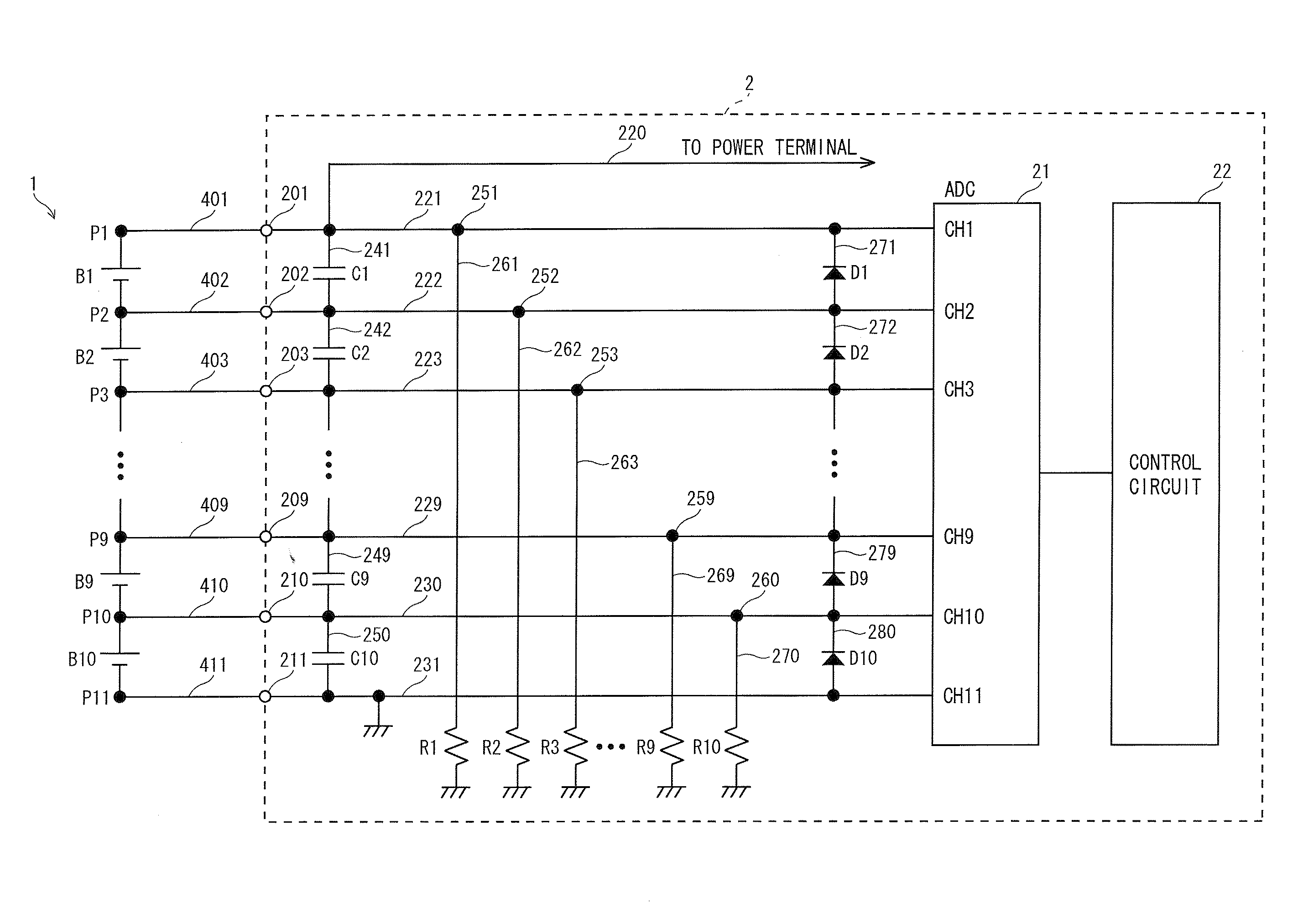
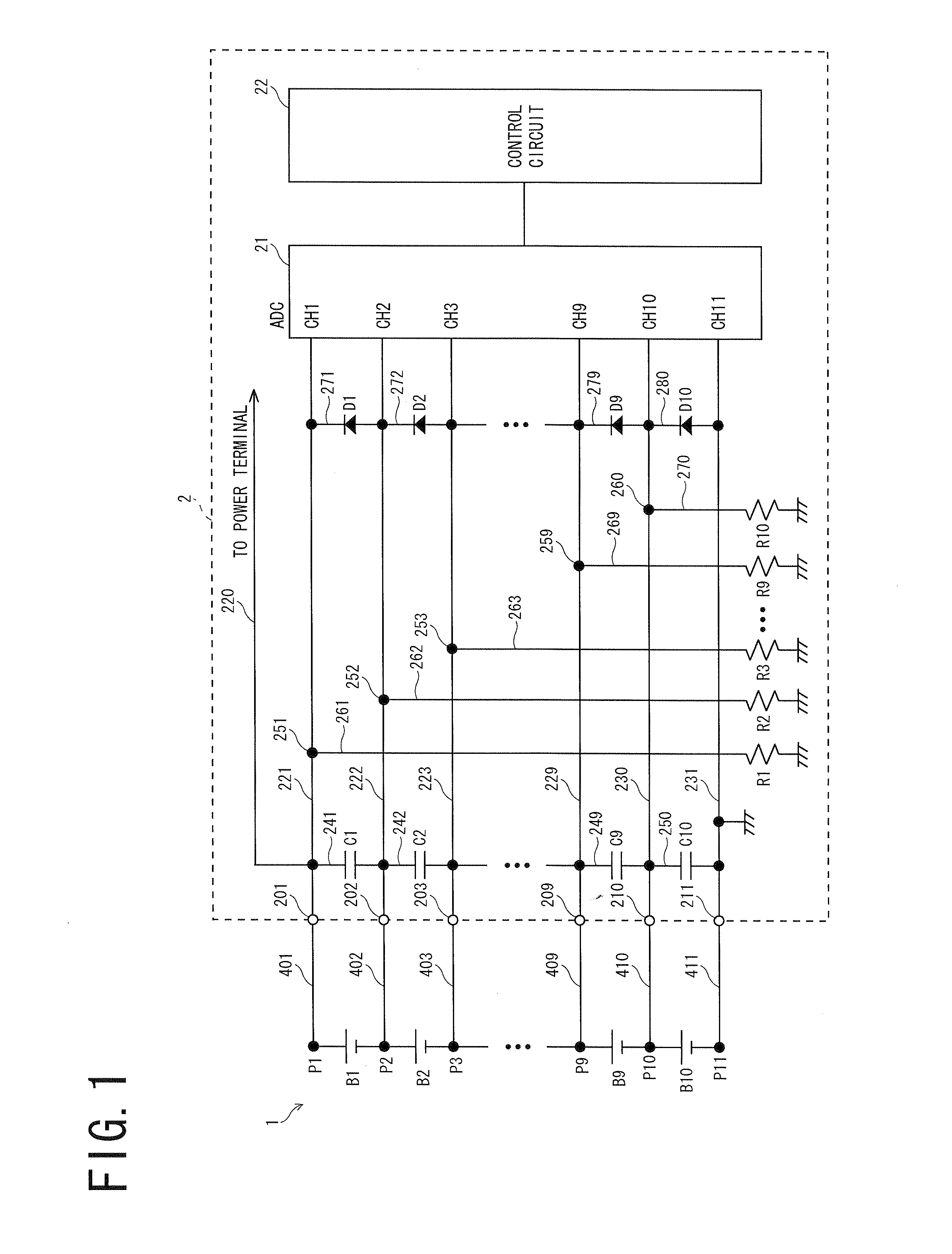
[0099]As shown in FIG. 1, a battery system according to a first embodiment comprises an assembled battery 1 comprising 10 lithium-ion secondary cells connected to each other in series, and a voltage detecting device 2 detecting the voltage across each of the cells. The assembled battery 1 has a positive electrode point P1, connecting points P2 to P10 between the cells, and a negative electrode point P11. The points P1 to P11 are respectively connected to 11 voltage input terminals 201 to 211 of the voltage detecting device 2 via wire harnesses 401 to 411. A power supply line (not shown) extends from each of the positive and negative electrodes of the assembled battery 1 to be connected to a load such as a drive motor.

[0100]In the voltage detecting device 2, voltage detecting lines 221 to 231 extend from the 11 voltage input terminals 201 to 211 respectively. Capacitors C1 to C10 for protecting circuits from static electricity voltage are respectively interposed on coupling lines 241...

second embodiment

[0113]As shown in FIG. 5, a battery system of this embodiment comprises an assembled battery 1 comprising 10 lithium-ion secondary cells connected to each other in series, and a voltage detecting device 20 detecting the voltage across each of the cells in the similar manner to the first embodiment. The assembled battery 1 has a positive electrode point Pi, connecting points P2 to P10 between the cells, and a negative electrode point P11. The points P1 to P11 are respectively connected to 11 voltage input terminals 201 to 211 of the voltage detecting device 20 via wire harnesses 401 to 411. A power supply line (not shown) extends from each of the positive and negative electrodes of the assembled battery to be connected to a load such as a drive motor.

[0114]The voltage detecting device 20 has 11 voltage detecting lines 221 to 231. Current lines 281 to 290 respectively extend from the points 251 to 260 on the voltage detecting lines 221 to 230 other than the 11th voltage detecting line...

third embodiment

[0118]As shown in FIG. 6, a battery system of this embodiment comprises an assembled battery 1 comprising 10 lithium-ion secondary cells connected to each other in series, and a voltage detecting device 5 detecting the voltage across each of the cells. The assembled battery has a positive electrode point P1, connecting points P2 to P10 between the cells, and a negative electrode point P11. The points P1 to P11 are respectively connected to 11 voltage input terminals 501 to 511 of the voltage detecting device 5 via wire harnesses 401 to 411. A power supply line (not shown) extends from each of the positive and negative electrodes of the assembled battery to be connected to a load such as a drive motor.

[0119]In the voltage detecting device 5, voltage detecting lines 521 to 531 extend from the 11 voltage input terminals 501 to 511 respectively. Capacitors C1 to C10 for protecting circuits from static electricity voltage are respectively interposed on coupling lines 541 to 550 coupling ...


PUM


Abstract

In the voltage detecting device according to the present invention, voltage detecting lines respectively extend from a plurality of voltage input terminals, a plurality of capacitative elements are respectively interposed on coupling lines each coupling two adjacent voltage detecting lines to each other, and the voltage detecting lines are connected to a voltage detecting unit. At least all the voltage detecting lines respectively disposed on the positive electrode side of the cells are each connected to ground via one or more disconnection detection resistors. The voltage detecting unit detects a disconnection on a wire between each of a plurality of voltage detecting points of the assembled battery and a plurality of voltage input terminals based on voltage inputted from each voltage detecting line.

Description

[0001]The applications Number 2008-157578 and 2009-140687 upon which this patent application is based, are hereby incorporated by reference.BACKGROUND OF THE INVENTION[0002]1. Field of the Invention[0003]The present invention relates to a device detecting a voltage across each of a plurality of cells connected to each other in series to form an assembled battery, and particularly to a voltage detecting device capable of detecting disconnection of a wire between the assembled battery and the device, and an assembled battery system comprising such a device.[0004]2. Description of Related Art[0005]Conventionally, a hybrid vehicle has an assembled battery comprising a plurality of lithium-ion secondary cells connected to each other in series mounted thereon as a power source of a drive motor. However, in such a conventional assembled battery, smoke emission or ignition may occur when the cells forming the assembled battery are overcharged or overdischarged. In view of this, it has been ...

Claims


Application Information

Patent Timeline
IPC IPC(8): H02J7/00G01R19/00G01R31/36G01R31/58H02J7/02
CPCG01R31/026G01R31/362Y02T10/7055H02J7/0016G01R31/3658G01R31/396G01R31/3835G01R31/54Y02T10/70G01R31/58
Inventor KUNIMITSU, TOMONORI
Owner SANYO ELECTRIC CO LTD
Why Eureka
Try Eureka