Light guide plate and backlight assembly having the same

Inactive Publication Date: 2009-12-17
SAMSUNG ELECTRONICS CO LTD
View PDF7 Cites 12 Cited by
  • Summary
  • Abstract
  • Description
  • Claims
  • Application Information

AI Technical Summary

Benefits of technology

[0014]According to the above, the light guide plate includes a plurality of light guide cells and at least one light source is aligned at

Problems solved by technology

The edge-illumination type backlight assembly has smaller thickness, but the number of light sources that can be used with this configuration is limited as compared

Method used


Image

  • Light guide plate and backlight assembly having the same
  • Light guide plate and backlight assembly having the same
  • Light guide plate and backlight assembly having the same

Examples


Embodiment Construction

[0030]Hereinafter, the present invention will be explained in detail with reference to the accompanying drawings.

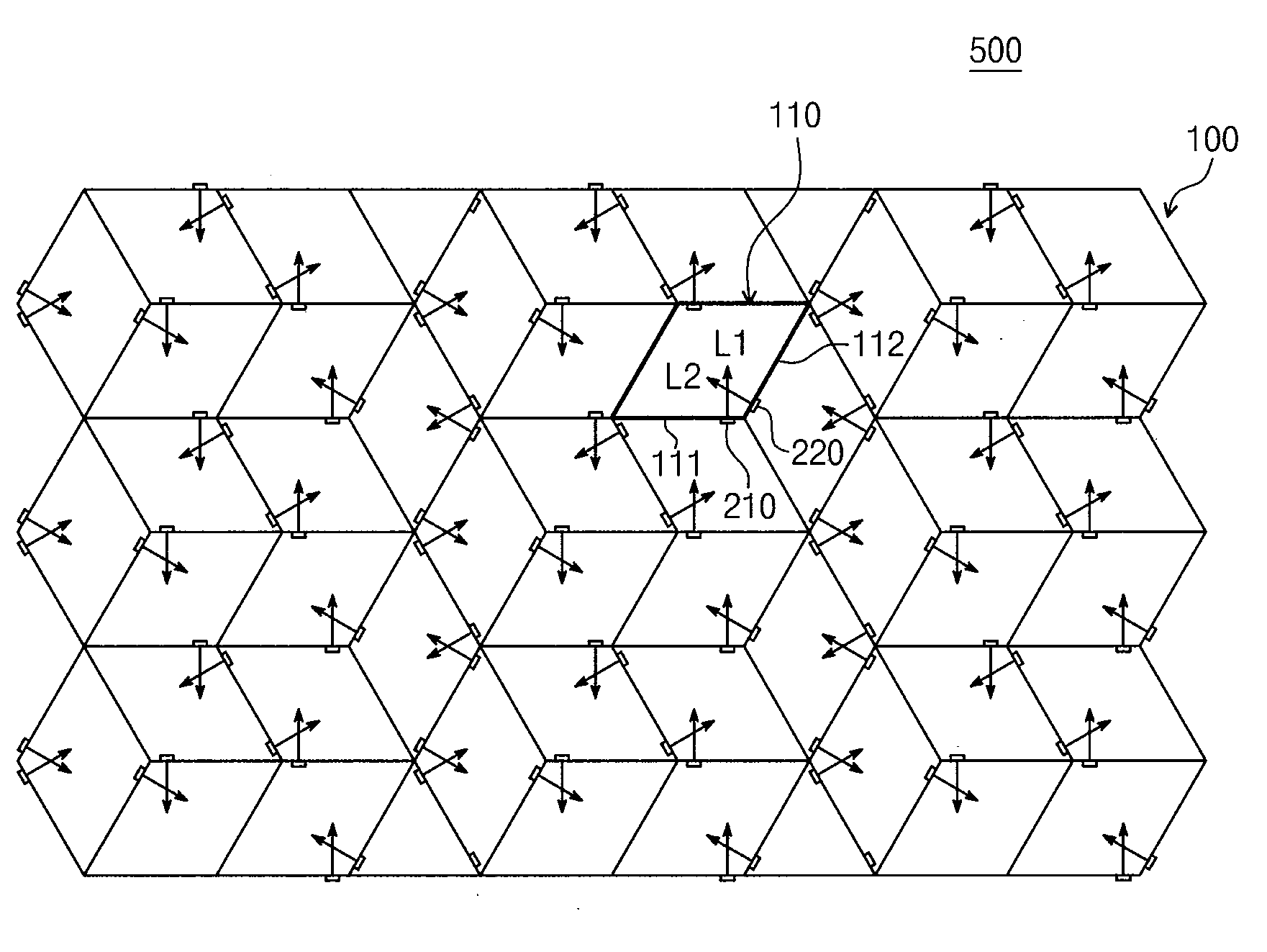
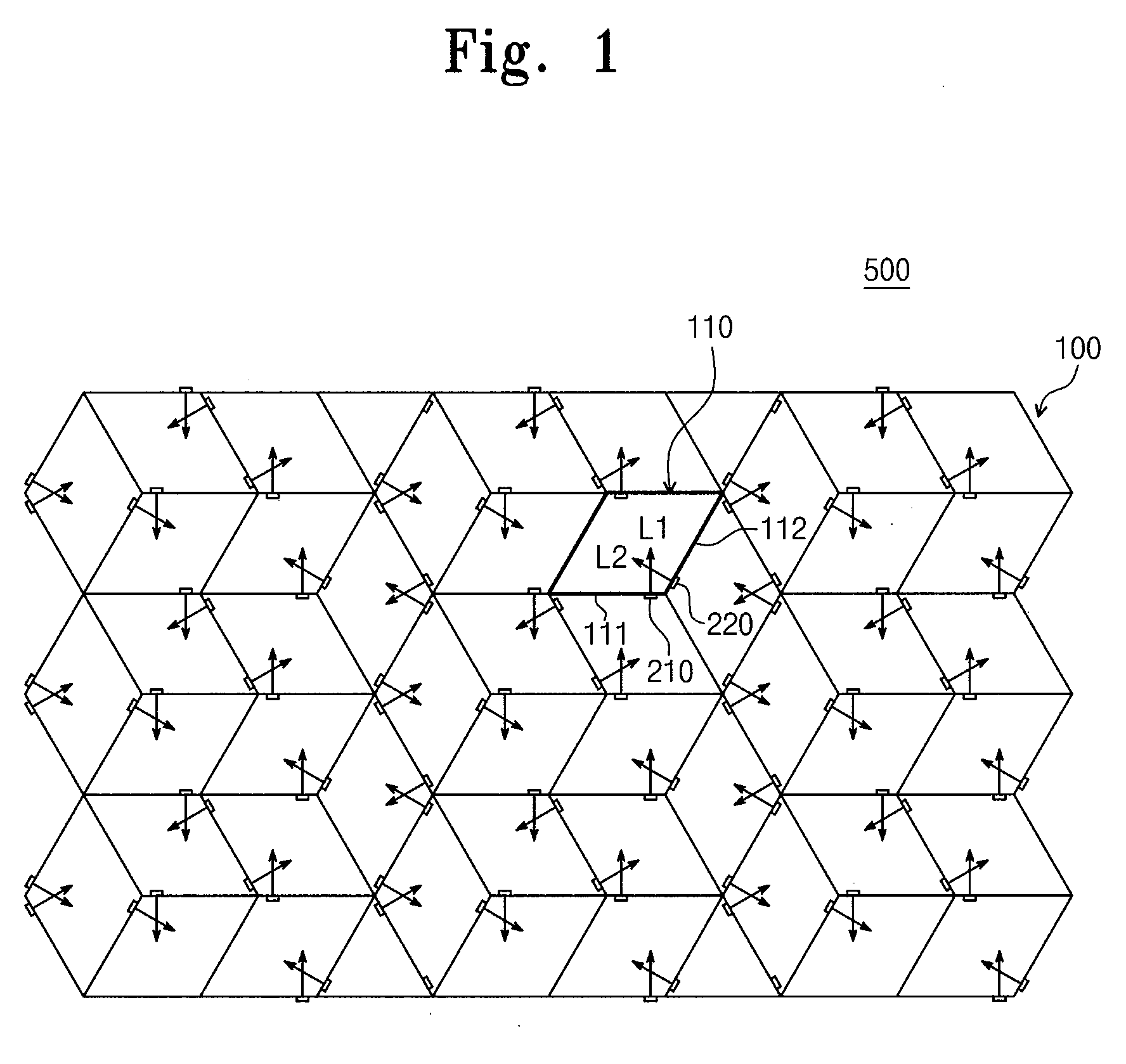
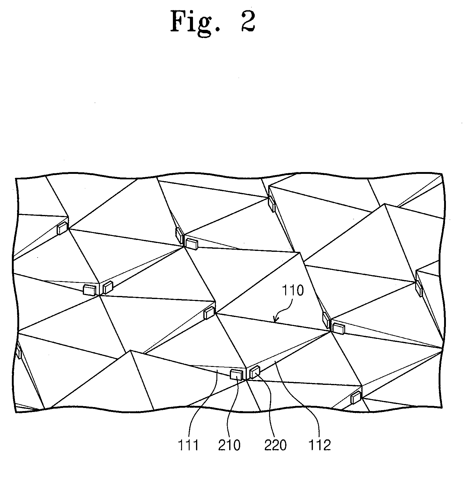
[0031]FIG. 1 is a rear view showing an exemplary embodiment of a light guide plate according to the present invention, and FIG. 2 is a partially-enlarged perspective view of the light guide plate shown in FIG. 1.

[0032]Referring to FIGS. 1 and 2, a backlight assembly 500 includes a light guide plate 100 and a plurality of light emitting diodes (LEDs) 210 and 220 installed at a rear surface of the light guide plate 100.

[0033]The light guide plate 100 includes a plurality of light guide cells 110 that are integrally formed with each other. Each light guide cell 110 includes first and second LEDs 210 and 220 that emit light in different directions. Each light guide cell 110 has first and second incident surfaces 111 and 112 to receive first and second lights L1 and L2 emitted from the first and second LEDs 210 and 220. The first and second incident surfaces 111 and 112 of the...


PUM


Abstract

In a light guide plate and a backlight assembly having the same, the light guide plate includes a plurality of light guide cells. Each light guide cell has at least one incident surface that receives light from an outside light source. The incident surfaces of the light guide cells are arranged in non-parallel planes. A light source unit includes at least one light source adjacent to the incident surface of each light guide cell. Thus, brightness of the backlight assembly is improved and thickness of the backlight assembly is reduced.

Description

CROSS-REFERENCE TO RELATED APPLICATION[0001]This application relies for priority upon Korean Patent Application No. 2008-56903 filed on Jun. 17, 2008, the contents of which are herein incorporated by reference in their entirety.BACKGROUND[0002]1. Field of the Invention[0003]The present invention relates to a light guide plate and a backlight assembly having the same. More particularly, the present invention relates to a light guide plate capable of reducing thickness of the backlight assembly and a backlight assembly incorporating the light guide plate.[0004]2. Description of the Related Art[0005]In general, a liquid crystal display (LCD) displays images by using optical characteristics of liquid crystal. Since the LCD uses liquid crystals, which are not self-emissive in themselves, a backlight assembly is positioned behind a liquid crystal display panel to provide light to the liquid crystal display panel. The liquid crystal display panel displays images using the light from the ba...

Claims


Application Information

Patent Timeline
IPC IPC(8): G02B6/00F21V8/00
CPCG02B6/0018G02B6/0043G02B6/0078G02B6/0055G02B6/0068G02B6/0046G02B6/00G02F1/1335
Inventor YOON, BYUNG-SEOHWANG, IN-SUNKIM, HEU-GONCHANG, MOON-HWANSHIN, TAEK-SUN
Owner SAMSUNG ELECTRONICS CO LTD
Why Eureka
Try Eureka