

Communication Node and Communication System
- Summary
- Abstract
- Description
- Claims
- Application Information
AI Technical Summary
Benefits of technology
Problems solved by technology
Method used
Image

Examples
first embodiment
1. First Embodiment
1-1. Network and Apparatus Configuration
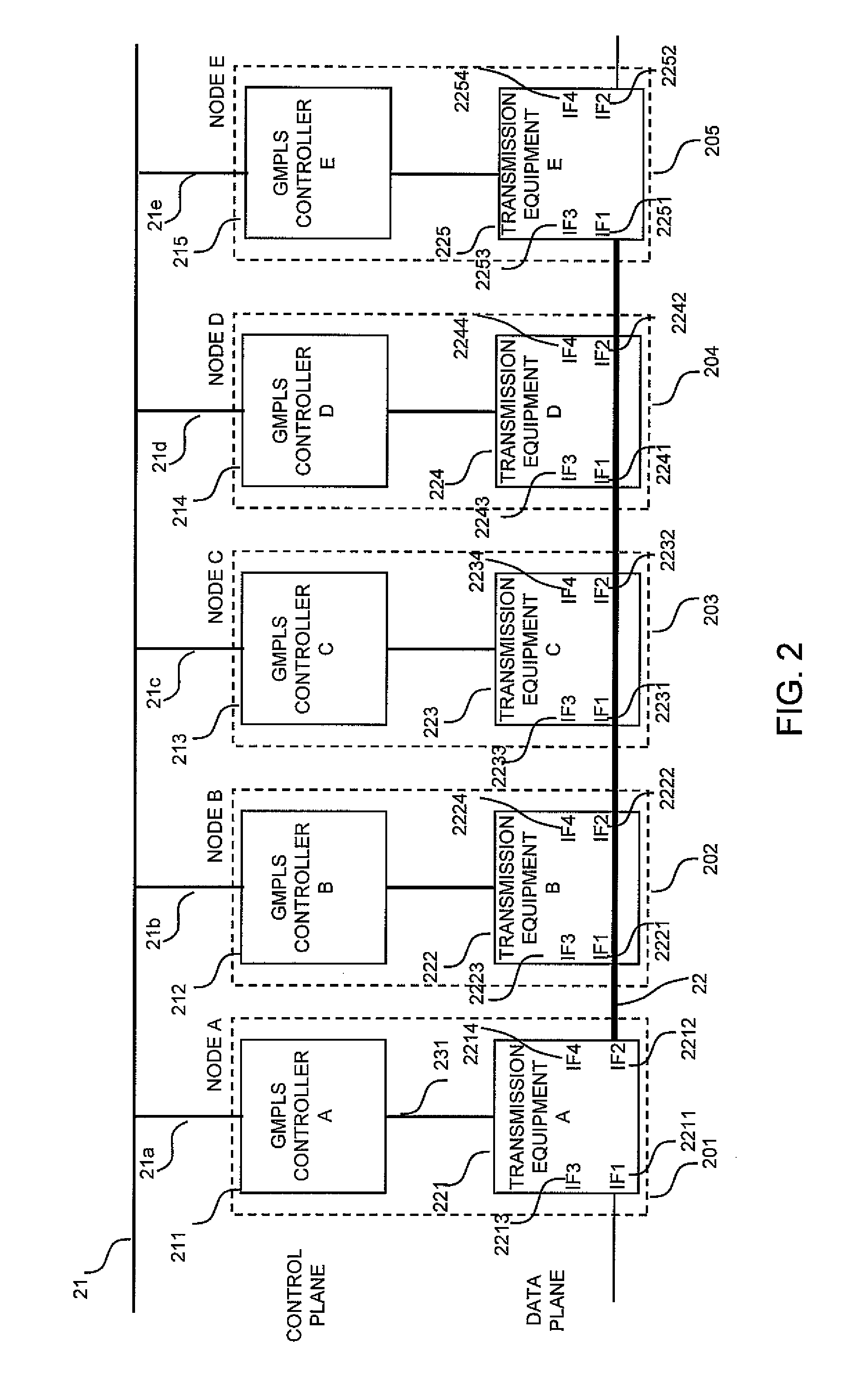
[0116]FIG. 2 is a configurational diagram of a network apparatus which is controlled with the GMPLS, in a first embodiment.
[0117]The network apparatus includes, for example, nodes A 201, B 202, C 203, D 204 and E 205, a network 21 (21a to 21e), and a data channel 22.
[0118]By way of example, when the network is configured of five transmission equipments A 221, B 222, C 223, D 224 and E 225 as shown in the figure, GMPLS controllers A 211, B 212, C 213, D 214 and E 215 which control the cross-connections of the respective transmission equipments A 221, B 222, C 223, D 224 and E 225 correspond in one-to-one correspondence. In this case, each of the nodes is formed of one transmission equipment and one GMPLS controller, and the respective nodes are set as the node A 201, node B 202, node C 203, node D 204 and node E 205. More specifically, the node A 201 has the GMPLS controller A 211, a transmission equipment A 221, and a trans...
second embodiment
2. Second Embodiment
[0186]A second embodiment is an example of a process which is involved in the communication fault of the control plane.
2-1. Network and Hardware Configuration
[0187]In the second embodiment, the network architecture shown in FIG. 2, the configuration of the GMPLS controller shown in FIG. 6, the configuration of the transmission equipment shown in FIG. 7, the formats of the individual state tables shown in FIGS. 8, 9, 10 and 11, and the state synchronization method for the GMPLS controller and the transmission equipment controller as shown in FIG. 12 are the same as in the first embodiment.
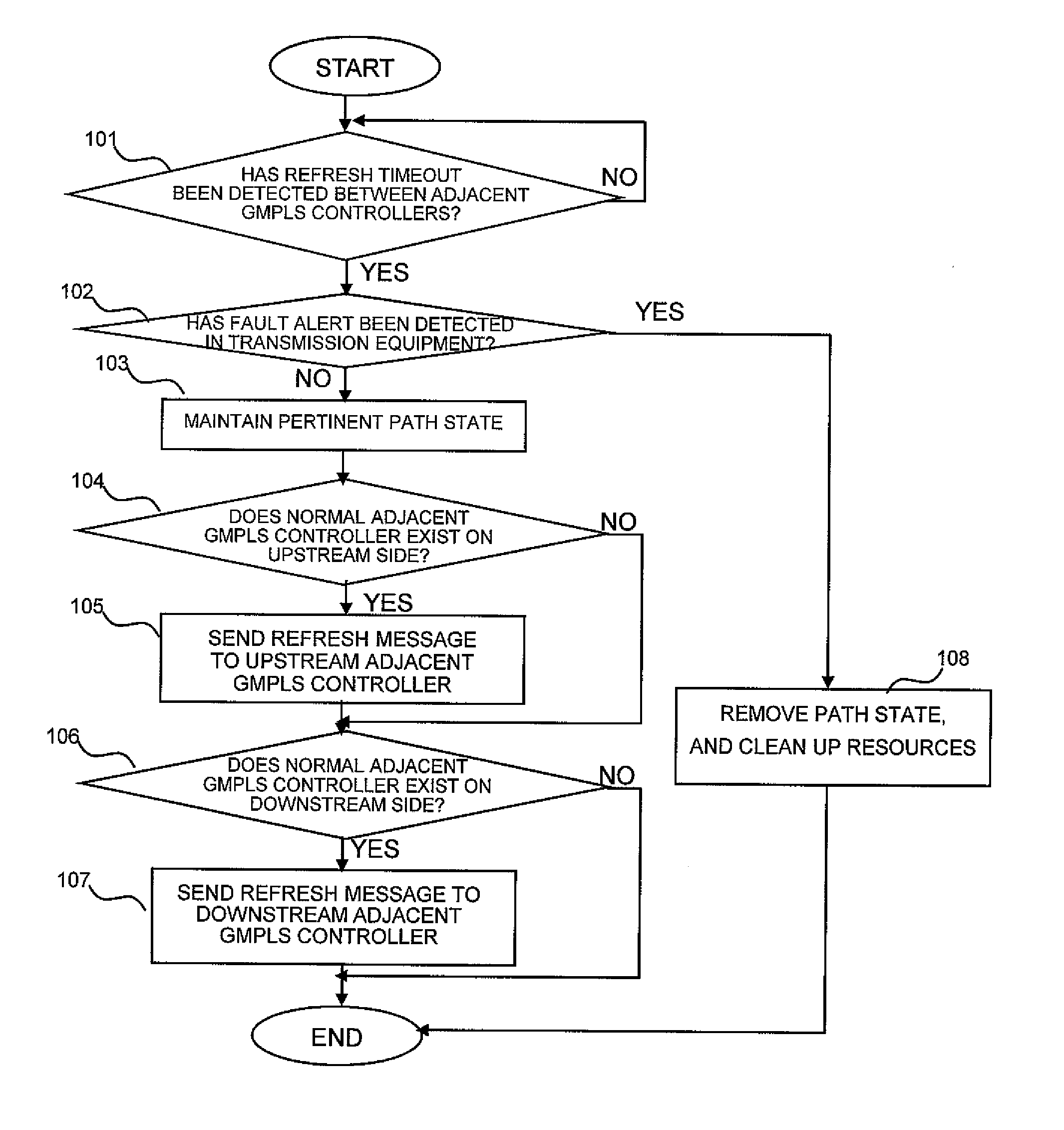
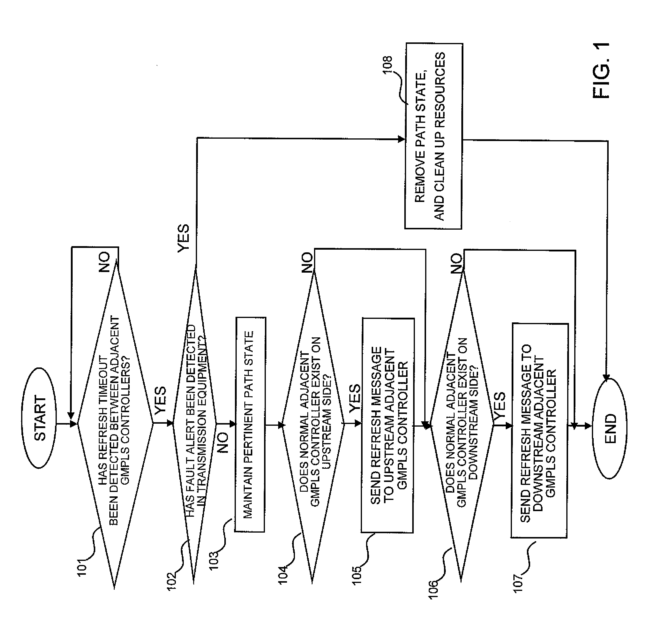
2-2. Flow Chart
[0188]A flow chart which the GMPLS controller 61 executes is the same as in the first embodiment.
2-3. Sequence (Communication Channel Fault of Control Plane)
[0189]The second embodiment differs from the first embodiment in that, unlike the fault of the GMPLS controller of the control plane, the fault has occurred on the communication channel of the control plane.
[...
third embodiment
3. Third Embodiment
[0205]A third embodiment is an example of an aspect in which information on a faulty node is notified to the ingress node of a path.
3-1. Network and Hardware Configuration
[0206]In the third embodiment, the network architecture shown in FIG. 2, the configuration of the GMPLS controller shown in FIG. 6, the configuration of the transmission equipment shown in FIG. 7, the formats of the individual state tables shown in FIGS. 8, 9, 10 and 11, and the state synchronization method for the GMPLS controller and the transmission equipment controller as shown in FIG. 12 are the same as in the first embodiment. However, a management table to be stated below is added.
[0207]FIG. 29 is a diagram for explaining the fault management table in the third embodiment.
[0208]The GMPLS controller A 211 of a node A being the ingress node registers notified faulty node information in the illustrated fault management table 290. Besides, the node A can previously grasp the fact that its own...
PUM
 Abstract
Description
Claims
Application Information