
Wireless communication system, connection device, relay device and registering method

a wireless communication system and relay device technology, applied in the field of wireless communication technology, can solve the problems of communication failure and data that cannot be relayed in the wireless communication system

Active Publication Date: 2009-12-17
BUFFALO CORP LTD
View PDF9 Cites 18 Cited by
  • Summary
  • Abstract
  • Description
  • Claims
  • Application Information

AI Technical Summary

Benefits of technology

[0008]Accordingly, it is an aspect of the present invention to provide a technology for relaying data between a wireless LAN and another LAN independently of a specific communication protocol.

Problems solved by technology

Since the above-described wireless communication system executes address conversion in the relay device using the table associating an IP address of a network layer address and a MAC address of a link layer address with each other, data that can be relayed in the wireless communication system is limited to data conforming to a specific communication protocol set in the relay device.
Therefore, if communication according to IPv6 is conducted through the relay device, a communication failure occurs.

Method used


Image

  • Wireless communication system, connection device, relay device and registering method
  • Wireless communication system, connection device, relay device and registering method
  • Wireless communication system, connection device, relay device and registering method

Examples


embodiment

A. Embodiment

[0026]A1. Configuration of a Wireless Communication System

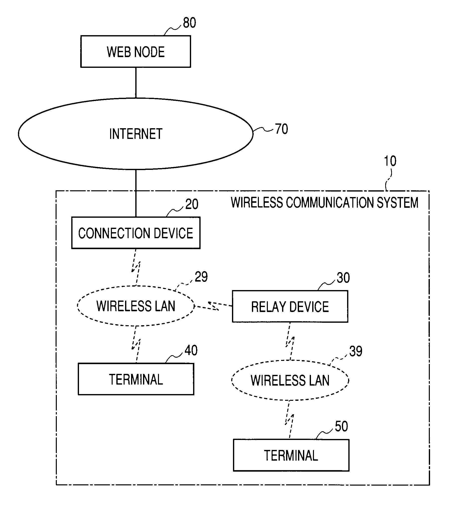
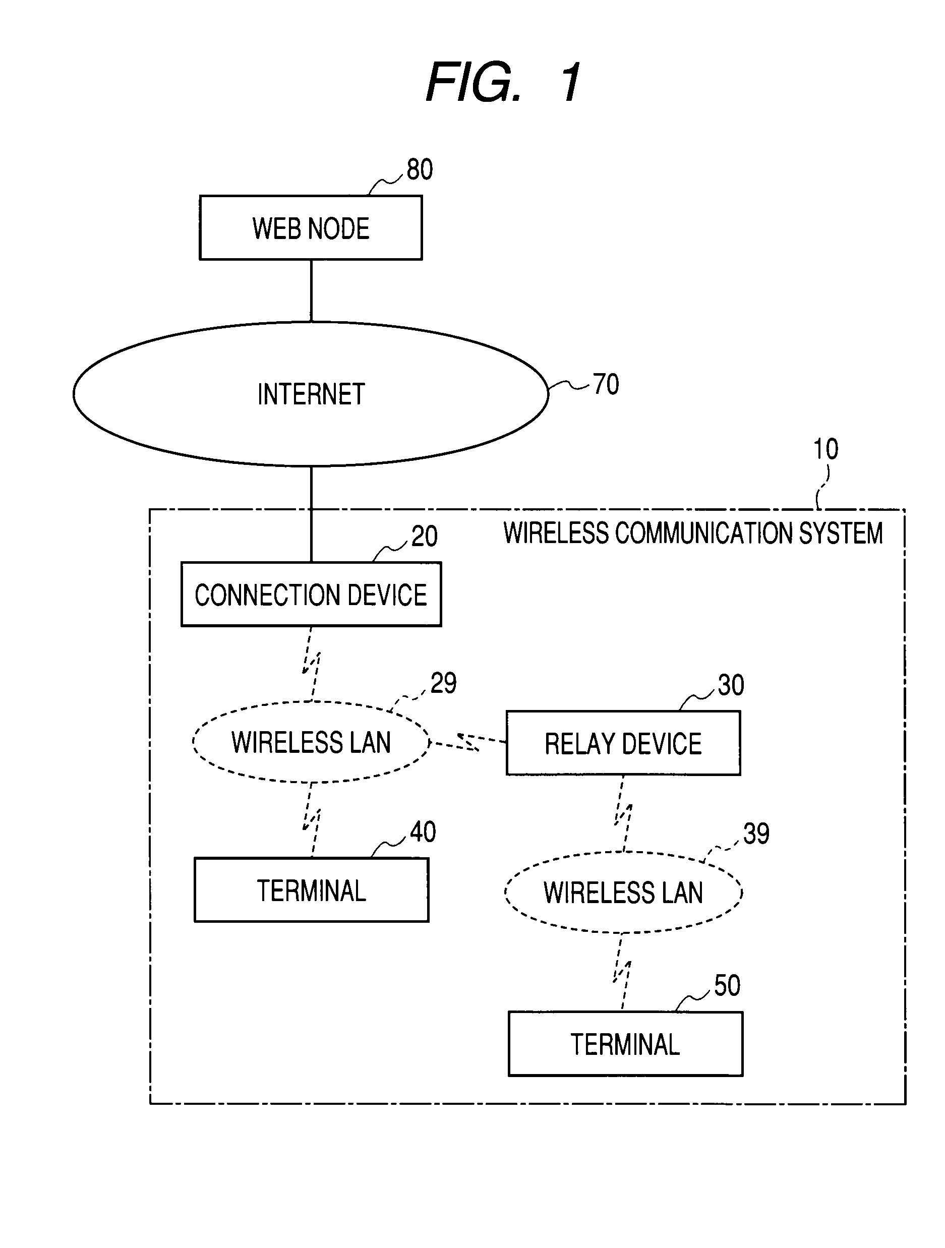
[0027]FIG. 1 is a schematic representation showing the configuration of a wireless communication system 10. The wireless communication system 10 includes a connection device 20, a relay device 30, and terminals 40 and 50. The connection device 20, the relay device 30, and the terminals 40 and 50 in the wireless communication system 10 are wireless LAN communication devices conforming to the IEEE802.11 standard.

[0028]The connection device 20 of the wireless communication system 10 is a wireless LAN connection device also called as a wireless LAN access point. The connection device 20 configures a wireless LAN 29 conforming to the IEEE802.11 standard. In the embodiment, the relay device 30 and the terminal 40 are connected to the wireless LAN 29 configured by the connection device 20. The connection device 20 has a routing function for connecting the wireless LAN 29 to the Internet 70 as an external network of the ...


PUM


Abstract

A wireless communication system is provided. The wireless communication system includes a connection device which configures a first LAN which is a wireless LAN; a relay device which configures a second LAN different from the first LAN and relays data between a LAN terminal connected to the second LAN and the connection device; an authentication connection section which connects the relay device to the connection device through the first LAN by executing authentication conforming to an infrastructure mode based on a request from the relay device to the connection device; and a data transfer section which transfers data to be communicated between the LAN terminal and the connection device by using a data frame conforming to a wireless distribution system between the connection device and the relay device connected by the authentication connection section.

Description

CROSS-REFERENCE TO RELATED APPLICATION[0001]This application claims priority from Japanese Patent Application No. 2008-158363, filed on Jun. 17, 2008, the entire subject matter of which is incorporated herein by reference.BACKGROUND OF THE INVENTION[0002]1. Field of the Invention[0003]The present invention relates to a wireless communication technology using a wireless local area network (LAN).[0004]2. Description of the Related Art[0005]A network configuration of a wireless LAN conforming to IEEE802.11 standard includes an infrastructure mode and a wireless distribution system (WDS) mode. A network in the infrastructure mode is configured between a base station for configuring a wireless LAN and a terminal station connected to the wireless LAN. A network in the WDS mode is configured between base stations.[0006]Japanese Patent Application Publication No. 2007-28124 describes a wireless communication system including a connection device as a first base station for configuring a firs...

Claims


Application Information

Patent Timeline
Patent Type & Authority Applications(United States)
IPC IPC(8): H04B7/14H04W4/00H04W12/06
CPCH04W12/06H04L63/08
Inventor TAMURA, YOSHITERU
Owner BUFFALO CORP LTD
Learn More