Impeller and centrifugal fan

a centrifugal fan and impeller technology, applied in wind motors with perpendicular air flow, waterborne vessels, machines/engines, etc., can solve the problems of increasing noise, increasing noise, and increasing the axial flow of air stream, so as to improve static pressure and flow rate characteristics, the effect of reducing the amount of nois

Active Publication Date: 2009-12-17
NIPPON DENSAN CORP
View PDF12 Cites 12 Cited by
  • Summary
  • Abstract
  • Description
  • Claims
  • Application Information

AI Technical Summary

Benefits of technology

[0009]In order to overcome the problems described above, preferred embodiments of the present invention provide an impeller and a centrifugal fan arranged to improve the static pressure and flow rate characteristics while enjoying a reduced amount of noise.

Problems solved by technology

This poses a problem in that improvement in one characteristic results in deterioration in the other.
The moving blades severely interfere with the axially flowing air stream in the vicinity of an intake port of the centrifugal fan.
Because of this, the increase in the number of moving blades entails a further problem in that the noise is increased by the interference of the moving blades with the air stream near the intake port.
Thus, the annular ring plate is apt to become an obstacle against the air stream generated by rotation of the impeller.
This may result in a deteriorated flow rate characteristic, increased noise, and other problems.

Method used


Image

  • Impeller and centrifugal fan
  • Impeller and centrifugal fan
  • Impeller and centrifugal fan

Examples


Embodiment Construction

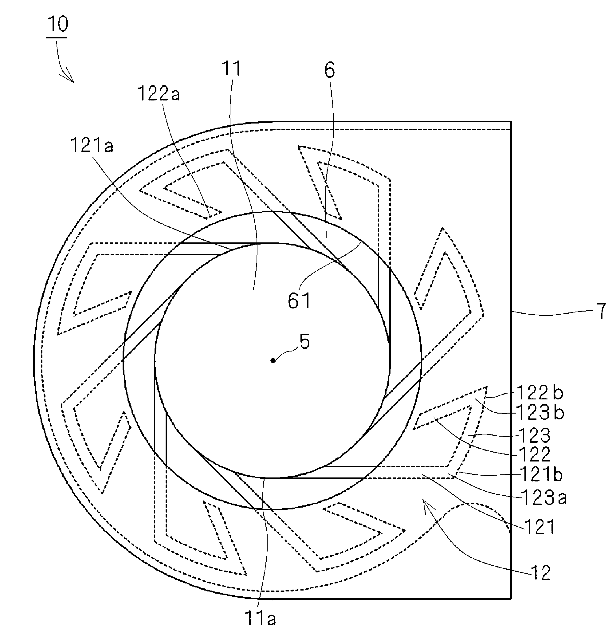
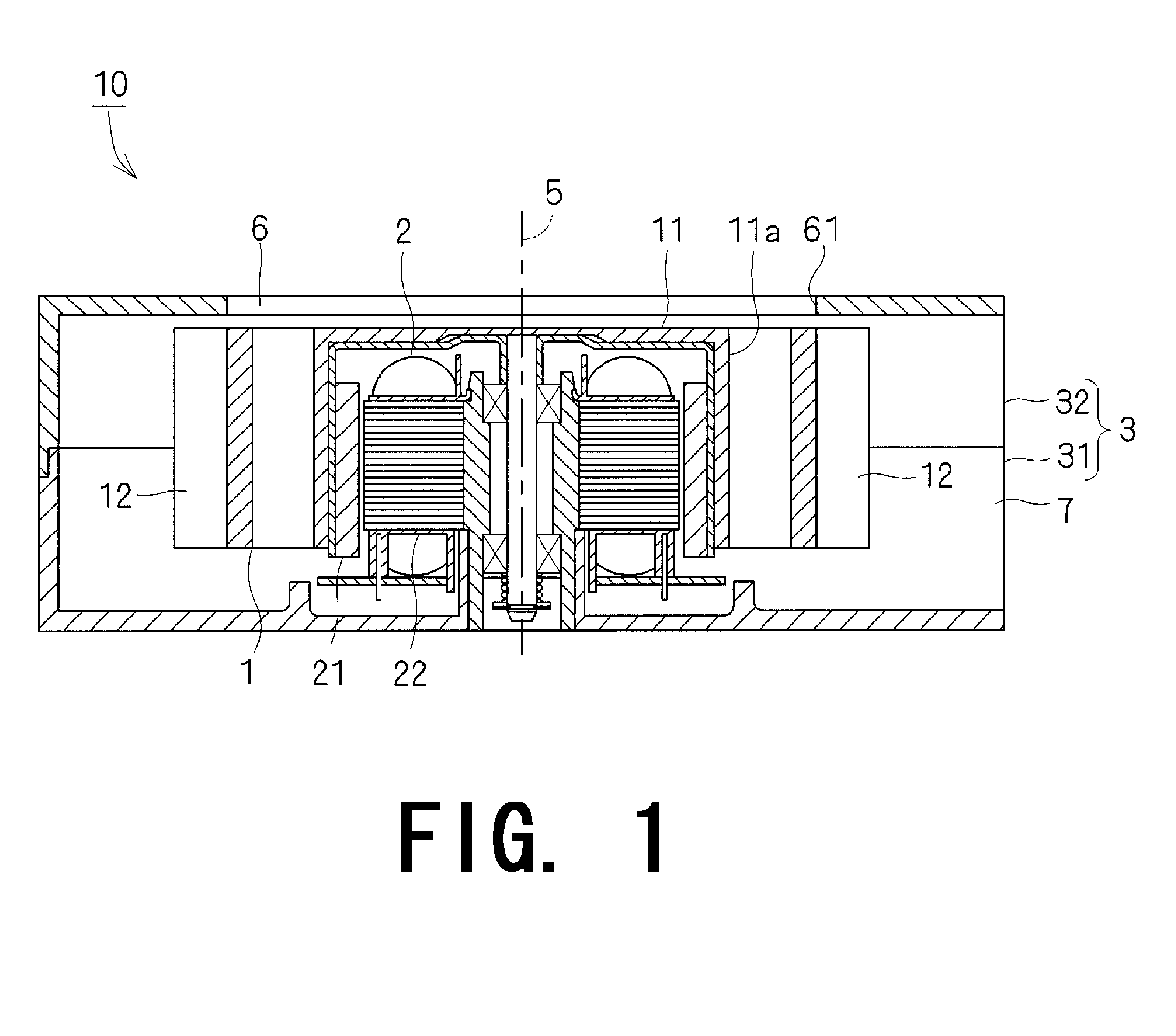
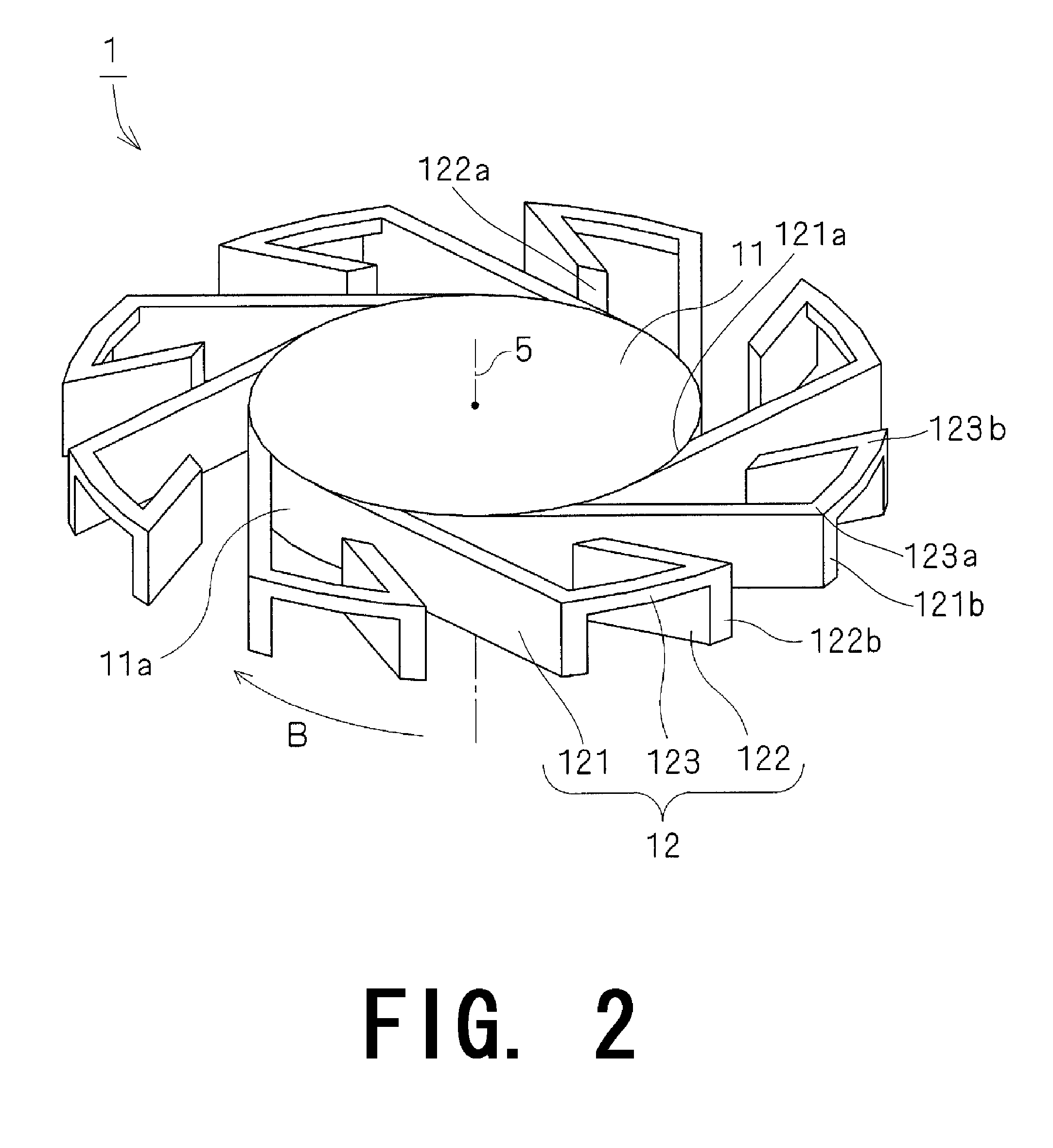
[0023]Preferred embodiments of the present invention will be described in detail with reference to FIGS. 1 through 11. It should be noted that in the explanation of the preferred embodiments of the present invention, when positional relationships among and orientations of the different components are described as being up / down or left / right, ultimately positional relationships and orientations that are in the drawings are indicated; positional relationships among and orientations of the components once having been assembled into an actual device are not indicated. Meanwhile, in the following description, an axial direction indicates a direction parallel or substantially parallel to a center axis 5, and a radial direction indicates a direction perpendicular or substantially perpendicular to the center axis 5. In the preferred embodiments, the upper side along the center axis 5 refers to the upper side in FIG. 1, while the lower side along the center axis 5 refers to the lower side in...


PUM


Abstract

An impeller in a centrifugal fan includes a support portion having a cylindrical outer circumferential surface coaxial or substantially coaxial with a center axis and a plurality of moving blades arranged on the outer circumferential surface of the support portion independently of one another and configured to draw an air along the center axis and expel the air radially outwards when rotated about the center axis together with the support portion. At least one of the moving blades includes a first blade portion connected to, and extending radially outwards from, the outer circumferential surface of the support portion, at least one second blade portion having a radial inner end portion radially spaced apart from the outer circumferential surface of the support portion and a connecting member arranged to interconnect the first blade portion and the second blade portion.

Description

BACKGROUND OF THE INVENTION[0001]1. Field of Invention[0002]The present invention relates to an impeller and a centrifugal fan.[0003]2. Description of the Related Art[0004]In recent years, electronic parts arranged within an electronic device tend to generate an increased amount of heat as the electronic devices achieve advanced performance. A centrifugal fan is often used in cooling the interior of the electronic device. In this case, the centrifugal fan is required to have an increased air-blowing ability in keeping with the increase in the amount of heat generated, while also assuring noise reduction.[0005]In order to increase the air-blowing ability of the centrifugal fan, there is a need to enhance the static pressure and flow rate characteristics thereof. The number of moving blades needs to be increased for the accomplishment of high static pressure but needs to be decreased for the accomplishment of high flow rate. In other words, the static pressure and the flow rate are in...

Claims


Application Information

Patent Timeline
Patent Type & Authority Applications(United States)
IPC IPC(8): F04D29/42F04D29/30
CPCF04D29/281F04D25/0613F04D29/30F05D2250/70
Inventor OTSUKI, TAKAYAAKASE, TATSUYATATSUNO, TSUNENORIFUKUNAGA, TOSHIKAZUTAKESHITA, KAZUMIOGASAWARA, TOMOHIKO
Owner NIPPON DENSAN CORP
Why Eureka
Try Eureka