Method of assembling captive screw

a technology of captive screw and assembly method, which is applied in the direction of threaded fasteners, manufacturing tools, bolts, etc., can solve the problems of increasing and achieve the effect of reducing the manufacturing cost of captive screws

Inactive Publication Date: 2009-12-24
FIVETECH TECH INC
View PDF27 Cites 13 Cited by
  • Summary
  • Abstract
  • Description
  • Claims
  • Application Information

AI Technical Summary

Benefits of technology

[0008]A primary object of the present invention is to provide a method of assembling captive screw that could be performed with the help of a relatively simple tool to reduce the manufacturing cost of the captive screw.

Problems solved by technology

Moreover, the above-described conventional method of assembling a captive screw requires the use of assembling tools with complicate structure, such as the push tool 2, the annular base 17, and the annular cutter 18, to thereby increase the manufacturing cost of the captive screw.

Method used


Image

  • Method of assembling captive screw
  • Method of assembling captive screw
  • Method of assembling captive screw

Examples


Embodiment Construction

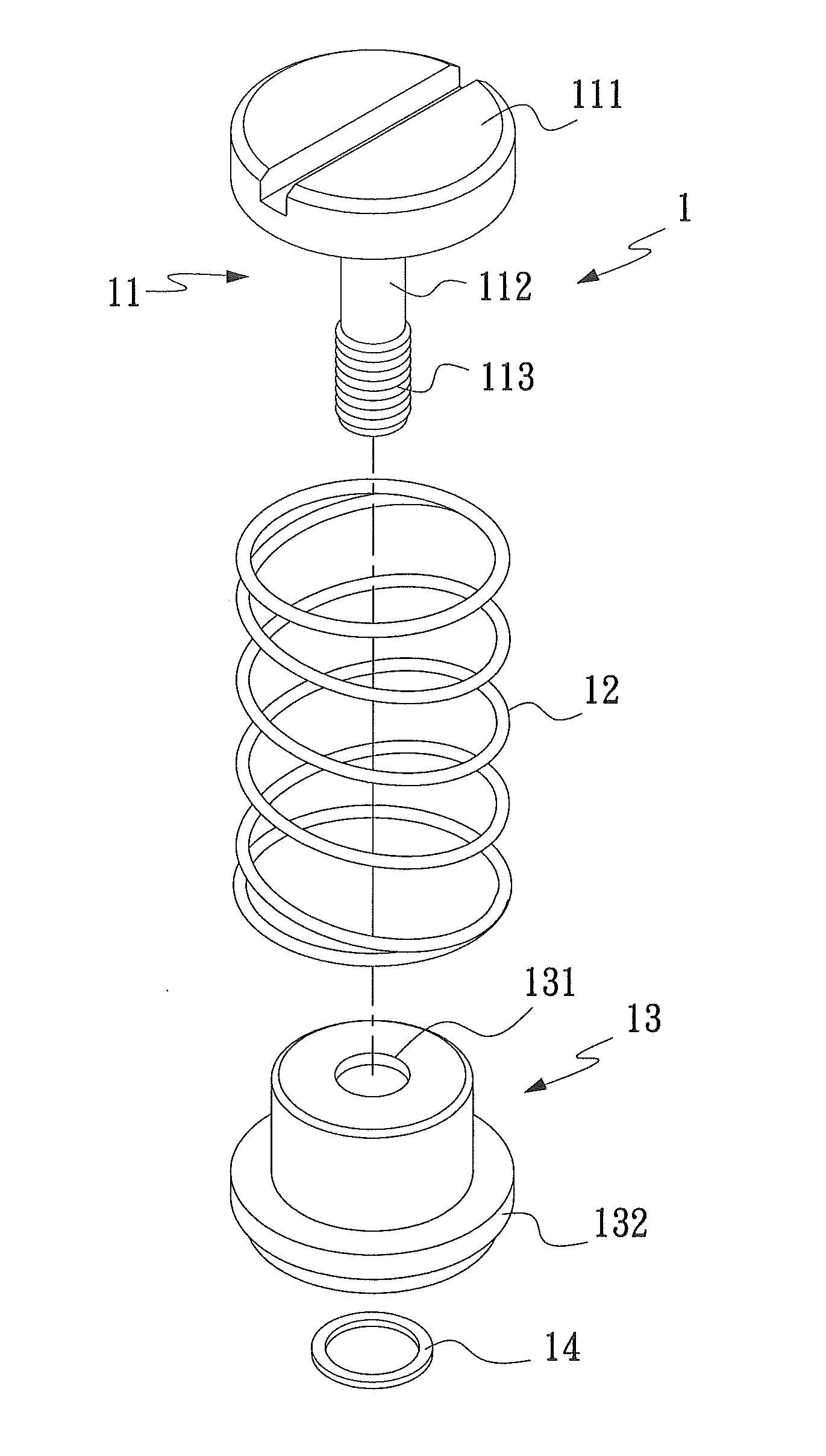
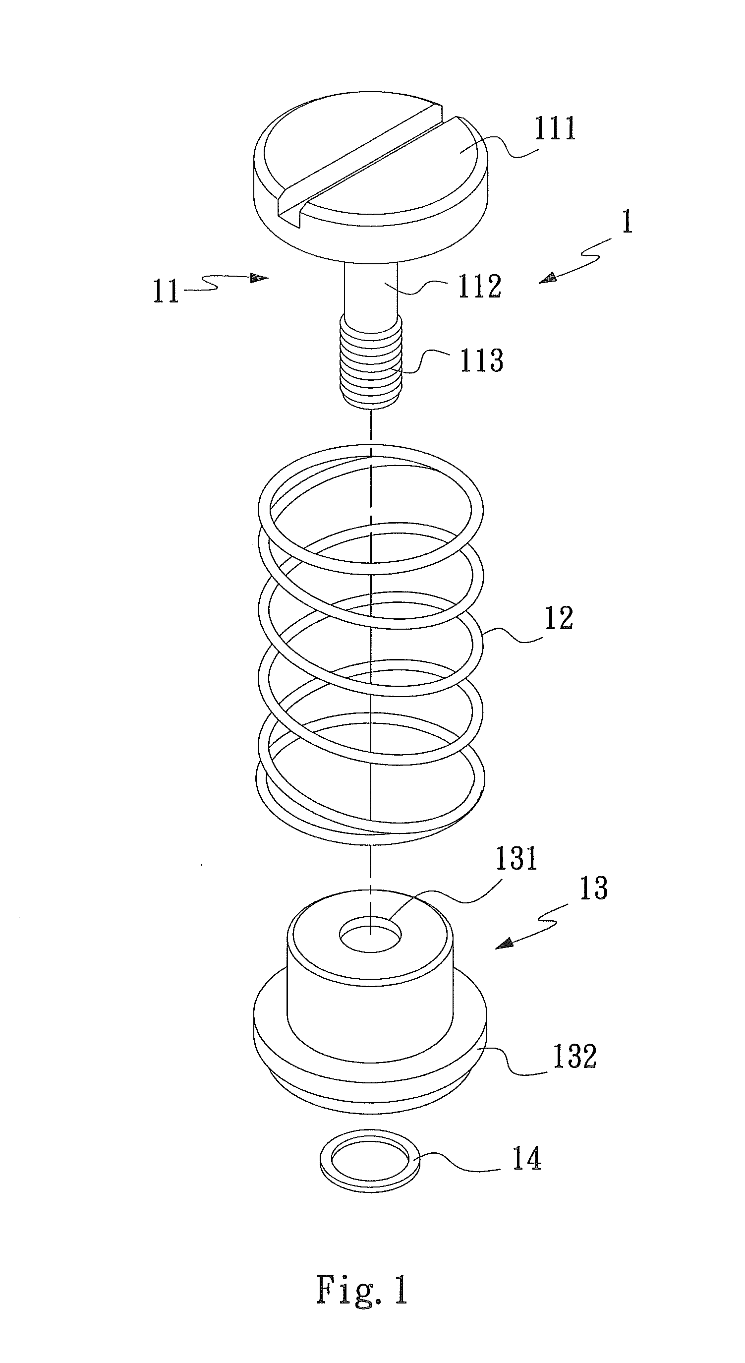
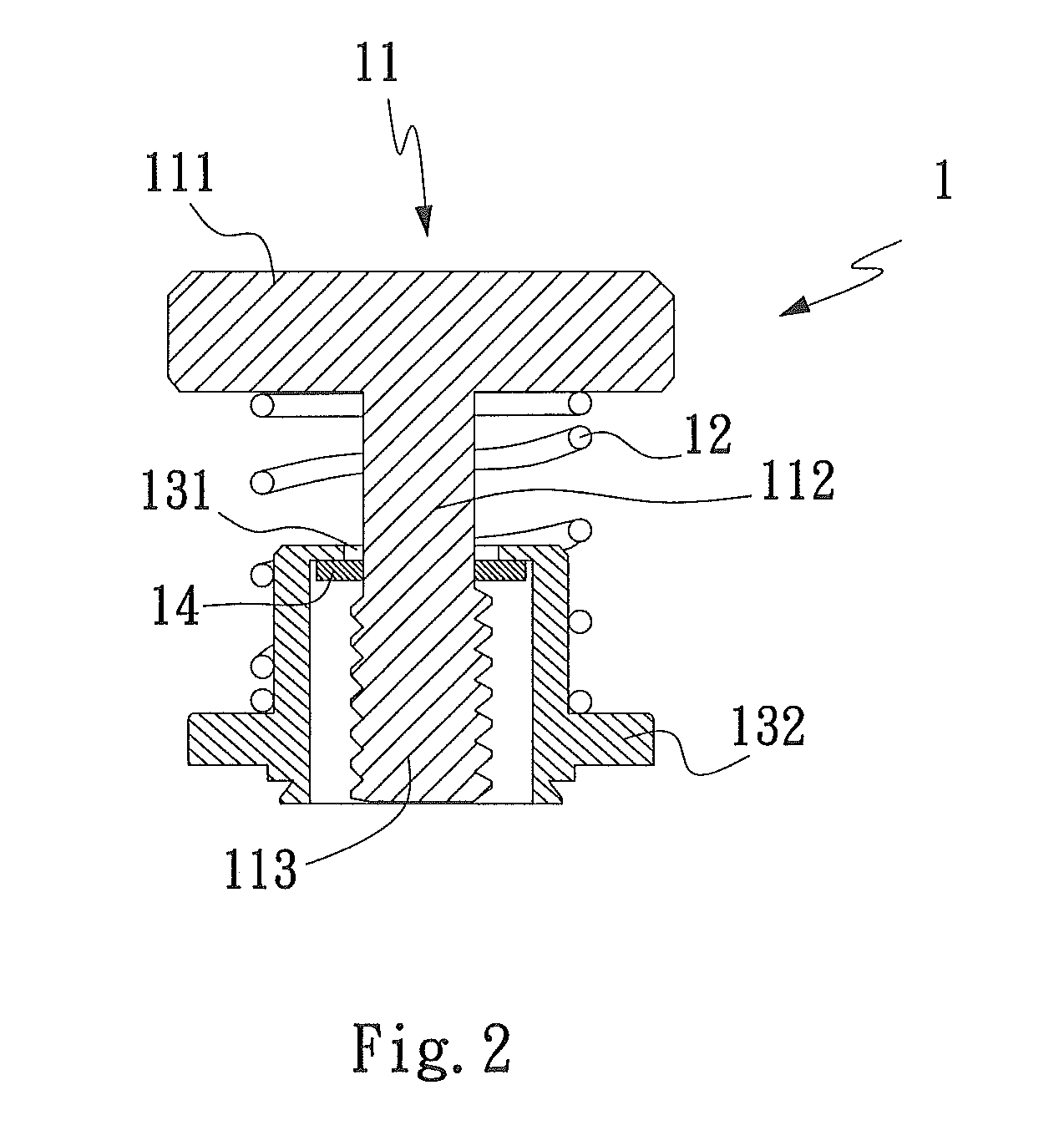
[0023]Please refer to FIGS. 7 through 11 that show a method of assembling captive screw according to a preferred embodiment of the present invention, and to FIG. 12 that is an enlarged view of the circled area in FIG. 11.

[0024]As shown, the method of assembling captive screw according to the present invention includes the following steps:[0025](1) provide a screw 11 and a sleeve 13; wherein the screw 11 includes from top to bottom a head 111, a shank 112, and a threaded section 113, and the sleeve 13 is provided a through opening 131;[0026](2) downward passed the threaded section 113 of the screw 11 through the through opening 131 on the sleeve 13; and[0027](3) cause helical screw threads on the threaded section 113 of the screw 11 to thread through an annular washer 14, so that the annular washer 14 is moved to and fitted around the shank 112 of the screw 11 to locate below the through opening 131 on the sleeve 13 and above an upper end of the threaded section 113 of the screw 11.

[...


PUM

PropertyMeasurementUnit
thicknessaaaaaaaaaa
inner diameteraaaaaaaaaa
sizeaaaaaaaaaa

Abstract

A method for assembling captive screw includes the steps of providing an annular base and positioning an annular washer on a top of the annular base; providing a screw, a coil spring, and a sleeve; downward passing the screw through the coil spring and a top opening of the sleeve; and threading a threaded section of the screw through the annular washer, so that the annular washer is fitted around a shank of the screw to locate below the top opening of the sleeve and above the threaded section of the screw. An inner circumferential edge of the annular washer is not worn away by the threaded section of the screw threaded therethrough, enabling the annular washer to keep a small inner diameter for tightly fitting around the shank of the screw and ensuring reliable assembling of the sleeve to the screw.

Description

CROSS-REFERENCE TO RELATED APPLICATIONS[0001]This application is a continuation-in-part patent application of U.S. application Ser. No. 12 / 022,203 filed on 30 Jan. 2008, the entire contents of which are hereby incorporated by reference for which priority is claimed under 35 U.S.C. § 120.FIELD OF THE INVENTION[0002]The present invention relates to a method of assembling a captive screw, and more particularly to a captive screw assembling method, in which a screw of the captive screw is passed through an annular washer by threading a threaded section of the screw through the annular washer instead of downward pressing the threaded section through the annular washer.BACKGROUND OF THE INVENTION[0003]FIGS. 1 and 2 are exploded perspective view and assembled sectional view, respectively, of a captive screw 1. As shown, the captive screw 1 includes a screw 11, a coil spring 12, a sleeve 13, and an annular washer 14. The screw 11 includes, from top to bottom, a head 111, a shank 112, and a ...

Claims


Application Information

Patent Timeline
Patent Type & Authority Applications(United States)
IPC IPC(8): B23P11/00
CPCF16B5/0208Y10T29/49963F16B41/002
Inventor WANG, TING-JUIWU, MING-DE
Owner FIVETECH TECH INC
Why Eureka
Try Eureka