Solar concentrator system

a concentrator system and solar energy technology, applied in the field of solar energy generation, can solve the problems of limited power output regulation of convex lens optical system for concentrator system, high cost of semi-conductor pv cells, and additional pv cells

Active Publication Date: 2009-12-24
KASK JANET L
View PDF36 Cites 31 Cited by
  • Summary
  • Abstract
  • Description
  • Claims
  • Application Information

AI Technical Summary

Benefits of technology

[0007]The present invention provides, in a first aspect, a solar energy concentrator system which includes a supporting structure and a plurality of solar modules coupled to the supporting structure. Each module of the plurality of solar modules includes a plurality of Fresnel reflectors. The plurality of reflectors is arranged to focus solar radiation linearly onto a photovoltaic cell or array of photovoltaic cells. The supporting structure is rotatably connected to a plurality of support members and aligned to allow the supporting structure to rotate about a polar axis. A plurality of optical trusses is connected to the plurality of solar modules and rotatably connected to the supporting structure to allow the plurality of solar modules to be rotated by the declination axis to track a motion of the of sun through seasons of the year.
[0008]The present invention provides, in a second aspect, a method for solar energy concentration which includes coupling a plurality of solar modules to a supporting structure. Each module of the solar modules includes a plurality of Fresnel reflectors. The plurality of reflectors is arranged to focus solar radiation linearly onto a photovoltaic cell or an array of photovoltaic cells. The supporting structure is rotatably connected to a plurality of support members and aligned to allow the supporting structure to rotate about a polar axis. A plurality of optical trusses is connected to the plurality of solar modules and rotatably connected to the supporting structure to allow the plurality of solar modules to be rotated about a declination axis to track a motion of the sun through seasons of the year.

Problems solved by technology

However, increasing the power output of a particular system requires additional PV cells, and large areas of semi-conductor PV cells are expensive.
Further, the scaling of convex lens optical systems for concentrator systems to regulate the amount of power output is limited by the mass of material needed to form a larger concentrator.
A paraboloid, however, tends to use a large amount of materials, is difficult to construct accurately while maintaining shape under varying gravity and wind loads, and requires a substantial structure for tracking the sun in the sky.

Method used


Image

  • Solar concentrator system
  • Solar concentrator system
  • Solar concentrator system

Examples


Embodiment Construction

[0015]In accordance with the principles of the present invention, a solar concentrator system and methods for concentrating solar energy to generate electricity are provided.

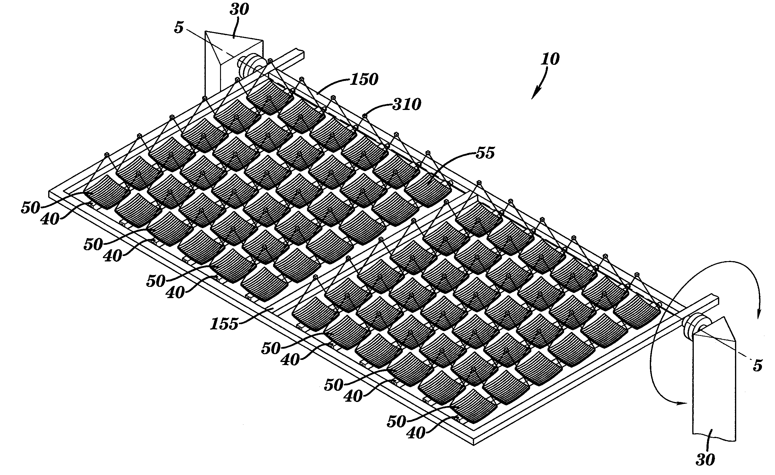
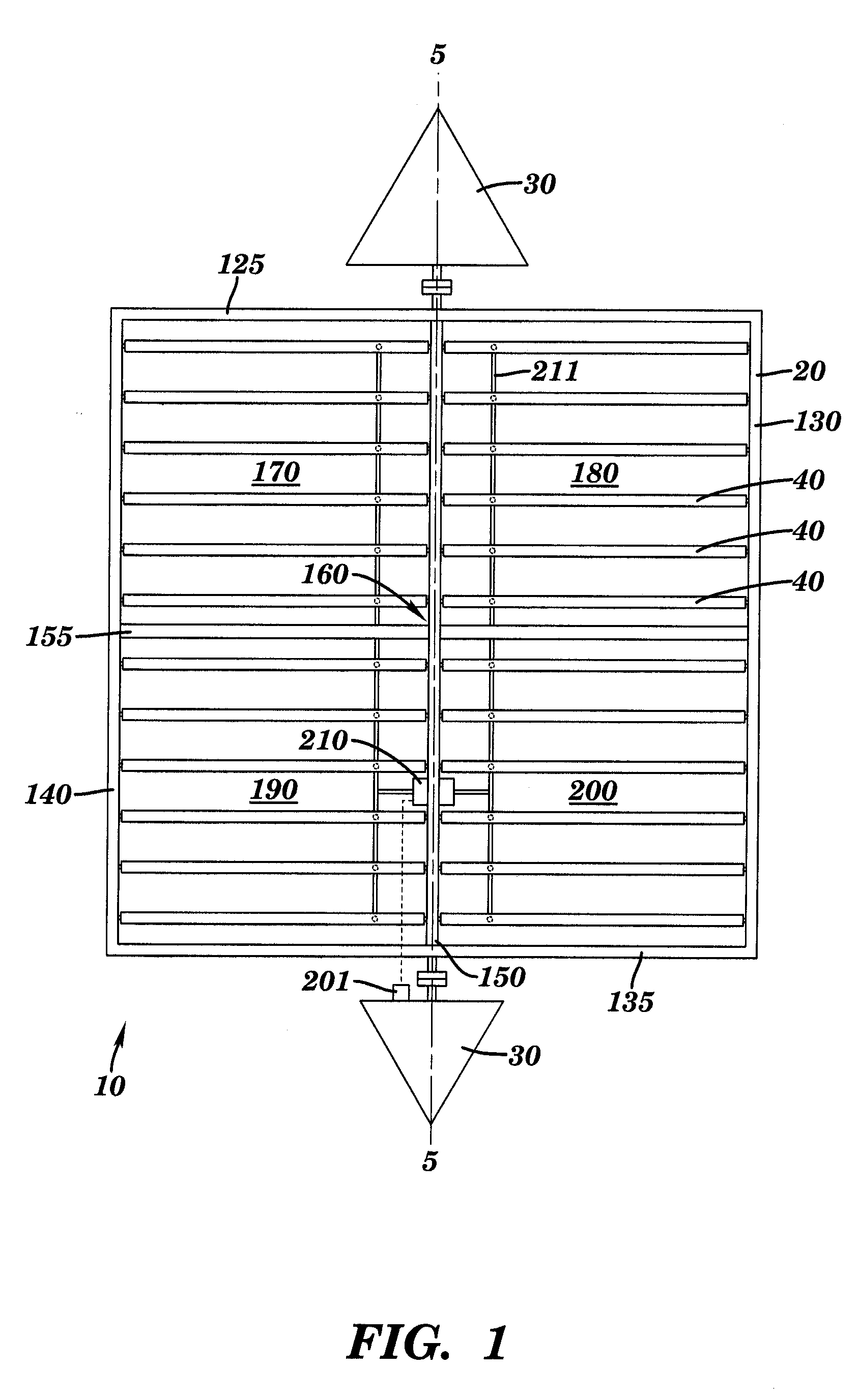
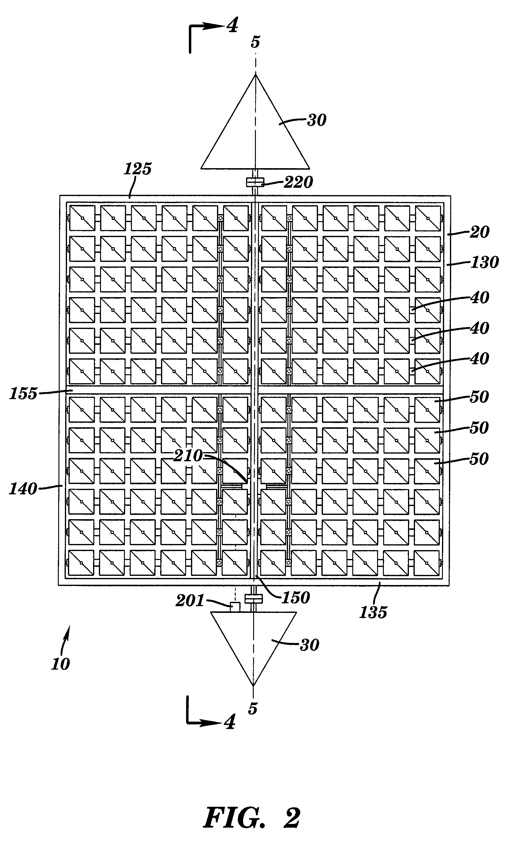
[0016]In an exemplary embodiment depicted in FIG. 1, a solar panel system 10 includes a supporting structure or frame 20 mounted on support members or towers 30. Frame 20 is rotatably connected to a plurality of optical trusses 40 which support a plurality of solar concentrator reflector modules 50.

[0017]As depicted in FIG. 1, frame 20 includes a North truss 125 opposite a South truss 135 and an East truss 130 opposite a West truss 140. A North-South connecting truss 150 connects North truss 125 to South truss 135. An East-West connecting truss 155 connects East truss 130 to West truss 140. East-West connecting truss 155 and North-south connecting truss 150 are connected to each other at a center area 160. System 10 is divided into four quadrants by the trusses depicted in FIG. 1: first quadrant 170, second quad...


PUM


Abstract

A solar energy concentrator system includes a supporting structure and a plurality of solar modules coupled to the supporting structure. Each module of the plurality of solar modules includes a plurality of Fresnel reflectors. The plurality of reflectors is arranged to focus solar radiation linearly onto a photovoltaic cell providing two axis concentration. The supporting structure is rotatably connected to a plurality of support members and aligned to allow the supporting structure to rotate about a polar axis. A plurality of optical trusses is connected to the plurality of solar modules and rotatably connected to the supporting structure to allow the plurality of solar modules to be rotated about a declination axis to track a motion of the sun through seasons of the year.

Description

TECHNICAL FIELD[0001]This invention relates, in general, to generating electricity from solar energy and, in particular, to systems and methods for concentrating solar energy to generate electricity.BACKGROUND ART[0002]Conventional photovoltaic (PV) systems generate electricity by direct exposure to the sun, i.e., they are designed for substantially 1-sun operation. In contrast concentrator PV systems rely on optical devices (e.g., mirrors) to concentrate more than one sun worth of solar radiation on a solar collector.[0003]Concentrator PV systems scale in size differently than conventional flat-plate photovoltaic systems, which are made for substantially 1-sun operation. Conventional PV is scaled by adding more panels (i.e., surface area) to generate different amounts of electricity. However, increasing the power output of a particular system requires additional PV cells, and large areas of semi-conductor PV cells are expensive. Concentrator PV uses optical devices to increase the ...

Claims


Application Information

Patent Timeline
Patent Type & Authority Applications(United States)
IPC IPC(8): H01L31/052G02B7/182
CPCF24J2/12F24J2/5427F24J2002/108F24J2002/1085G02B5/09H01L31/0547Y02E10/42Y02E10/47Y02E10/52H02S20/00F24J2/38G02B7/183F24S23/71F24S30/458F24S50/20F24S2023/872F24S2023/874H02S20/30H02S20/32H02S40/22Y02E10/40
Inventor BORTON, DAVID
Owner KASK JANET L
Why Eureka
Try Eureka