Solar power plant

a technology for solar power plants and solar panels, applied in the direction of dc-ac conversion without reversal, emergency protective arrangements for limiting excess voltage/current, fixed transformers, etc., can solve the problems of reducing the conversion efficiency of inverters, the cell of modules cannot accept voltages having a polarity to ground, and the shortening of the life of the battery

Active Publication Date: 2009-12-24
SMA SOLAR TECH AG
View PDF2 Cites 31 Cited by
  • Summary
  • Abstract
  • Description
  • Claims
  • Application Information

AI Technical Summary

Benefits of technology

[0015]The particular advantage of the invention is that photovoltaic generators may be utilized, which must be grounded for operation. The circuit arrangement of the invention may moreover be utilized with all the inverter topologies in large plants, which need a mains transformer of their own. Therefore, no special inverters must be utilized.
[0016]In accordance with the invention, a solar plant with at least one mains transformer is obtained, an additional direct voltage source being inserted between the neutral conductor (N) and the ground (PE), so that the potential of the one terminal of the photovoltaic string is set to a potential different from zero volts or greater than zero volts. This potential may also be a negative voltage though. Accordingly, the voltage must be different from zero volts. In height and polarity, the bias voltage adjusts to the desired potential of the photovoltaic string.
[0017]The invention moreover solves the grounding problem without the use of a galvanic isolating inverter or of a transformerless inverter of a certain circuit topology.
[0018]Using a three-phase inverter arrangement without a neutral conductor implementation, the direct voltage source can be inserted between one of the three phases L1, L2, L3 and PE. Using a three-phase inverter arrangement with a neutral conductor implementation, the direct voltage source is connected between the neutral conductor and PE. The midpoint of the transformer is connected to a neutral conductor. Again, the mains transformer is a multiphase transformer.
[0019]Other advantageous implementations of the invention are recited in the dependent claims.
[0020]In an advantageous development of the drive of the invention, there is provided that a current monitoring device of the additional direct voltage source for detecting a ground fault is connected. This allows for additionally monitoring a ground fault or a defective isolation at quite little expense in terms of circuitry, because the same current path, which leads to PE, can be used both for raising the potential and for measuring the current.

Problems solved by technology

Otherwise, early damage may occur to these modules, resulting in a shorter life.
As a result, the cells of the modules can only accept voltages having a polarity to ground.
This leads to a reduced conversion efficiency of these inverters.
This is intended to lengthen the life of the modules.
If the solar plant is big and has many photovoltaic generators and inverters, a large number of such devices should be mounted, which is expensive though.

Method used


Image

  • Solar power plant
  • Solar power plant
  • Solar power plant

Examples


Embodiment Construction

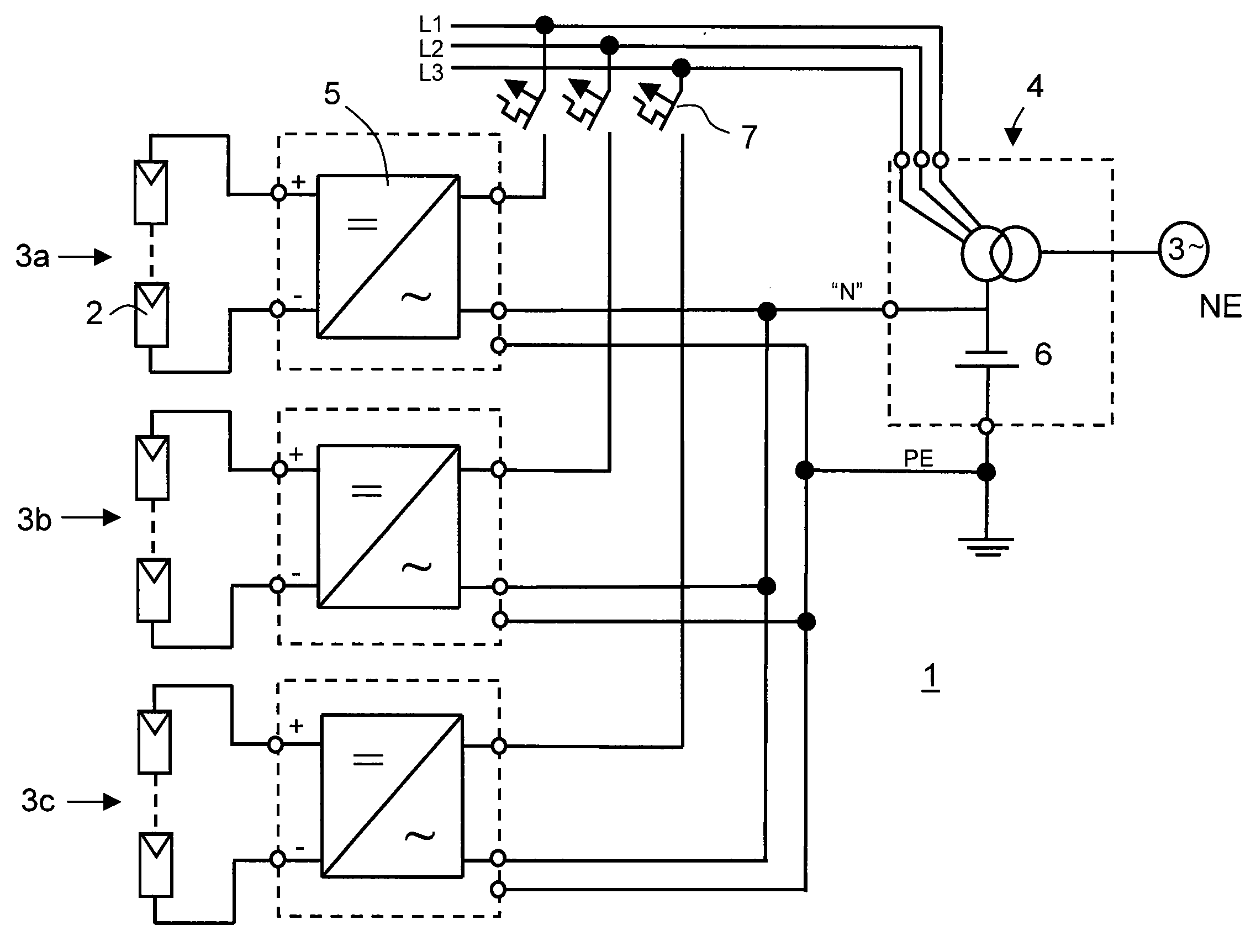
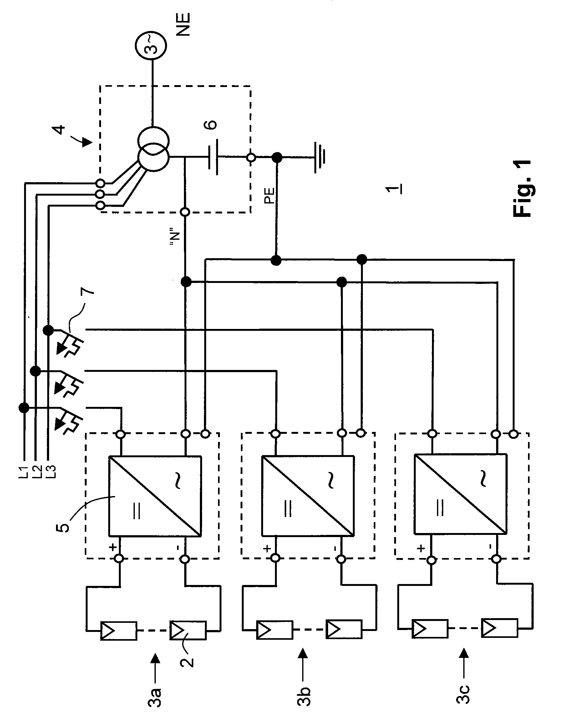
[0029]FIG. 1 shows a first embodiment of a solar power plant 1. The solar power plant incorporates a plurality of photovoltaic modules 2, in particular of thin-film modules for generating a power to be fed in a multiphase, in particular in a three-phase grid NE. Several photovoltaic strings 3a, 3b, 3c, which are allocated to different phases, are connected to a primary side of a mains transformer 4. Furthermore, there are provided several inverters 5, in particular transformerless inverters, for converting the direct voltage generated by the photovoltaic modules into a mains alternating voltage conforming to the grid. They may include boost and / or buck converters, a bridge circuit, a pulse-width control and / or an a maximum power point (MPP) control. The mains transformer 4 is provided with a neutral conductor N and with a grounded terminal PE.

[0030]The three one-phase inverters 5 are arranged such that feeding occurs in each phase of the three-phase mains transformer 4. For each pha...


PUM


Abstract

A solar power plant with a plurality of photovoltaic modules for generating a power to be fed in a multi-phase grid, several photovoltaic strings, which are allocated to different phases, being connected to a primary side of a mains transformer and at least one inverter for converting the direct voltage generated by the photovoltaic modules into an alternating mains voltage conforming to the grid being provided and said mains transformer being provided with a neutral conductor and with a grounded terminal, is intended to be improved in such a manner that the life of the photovoltaic modules, in particular in case of thin-film modules, is increased, allowing for high conversion efficiency of the inverters at low wiring costs. This is achieved in that an additional direct voltage source is inserted between the neutral conductor and ground in such a manner that the potential of the photovoltaic strings is displaced and that a bias voltage is set, which is different from zero volt.

Description

BACKGROUND OF THE INVENTION[0001]The invention relates to a solar power plant having a plurality of photovoltaic modules for generating power to be fed into a multiphase grid, several photovoltaic strings allocated to different phases being connected to a primary side of a mains transformer and at least one inverter for converting the direct voltage generated in the photovoltaic modules into a grid-complying alternating grid voltage being provided and the mains transformer being provided with a neutral conductor and with a grounded terminal or with a grounded terminal only.[0002]Big solar plants, which are referred to as solar power plants, consist of a plurality of solar modules or of photovoltaic modules and inverters. The photovoltaic modules acting as the generators are connected in series or in parallel to form what are referred to as strings. The inverters are wired so that they feed the grid via a joint mains transformer.[0003]In principle, one-phase or multi-phase inverters ...

Claims


Application Information

Patent Timeline
Patent Type & Authority Applications(United States)
IPC IPC(8): H02J5/00
CPCH02J3/383Y02E10/563H02J2300/24H02J3/381Y02E10/56H02J7/35H02H9/04H02M7/48
Inventor CRAMER, GUENTHERENGEL, BERNDGREIZER, FRANKLASCHINSKI, JOACHIM
Owner SMA SOLAR TECH AG
Why Eureka
Try Eureka