Electrical generators for low-frequency and time-varying rocking and rotary motion

Active Publication Date: 2009-12-24
OMNITEK PARTNERS LLC
View PDF9 Cites 37 Cited by
  • Summary
  • Abstract
  • Description
  • Claims
  • Application Information

AI Technical Summary

Benefits of technology

[0015]The electrical energy generators can be very simple, can efficiently operate over a very large ra

Problems solved by technology

In particular, there is a need for such electrical energy generators to operate without the need for costly speed increasing and regulating d

Method used


Image

  • Electrical generators for low-frequency and time-varying rocking and rotary motion
  • Electrical generators for low-frequency and time-varying rocking and rotary motion
  • Electrical generators for low-frequency and time-varying rocking and rotary motion

Examples


embodiment 30

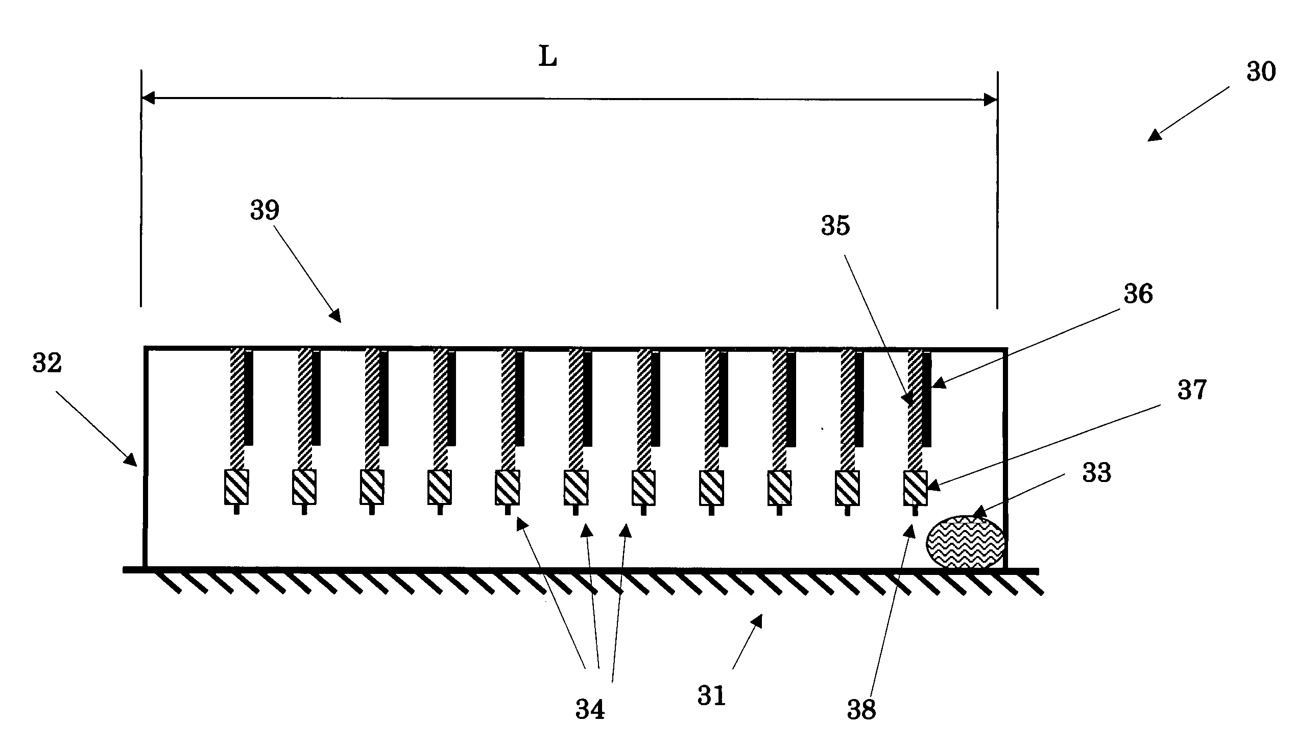
[0031]The above novel two-stage energy harvesting method for rocking platforms is best described by the following basic embodiment 30, which is shown schematically in FIG. 3. The primary system of the embodiment 30 consists of a simple housing 32, which is attached directly to the rocking platform 31. The rocking oscillation of the platform 31 is considered to be about an axis perpendicular to the plane of the page. As the platform 31 undergoes rotary oscillation, the traveling mass 33 begins to slide from the side that has been raised, travels the length of the housing 32 and ends on its opposite end of the housing. At least one secondary vibratory element 34 is attached to the top portion 39 of the housing 32. Each vibratory element consists of a relatively flexible beam 35, to the tip of which is preferably attached a mass 37 to allow for optimal tuning of the natural frequency of the first mode of vibration of the vibratory elements. The tip of the beam 35 and mass 37 assemblies...

embodiment 50

[0045]The schematic of a basic embodiment 50 of such a two-stage generator design for harvesting energy from slow and varying rotary motion is shown in FIG. 5. The generator consists of an outer housing 51, which is fixed, for example to a fixed structure 52. Internal to the housing is mounted at least one and preferably more secondary vibrating elements 55. In the schematic of FIG. 5, the secondary vibrating elements 55 are constructed as vibrating beam elements 56, over the surface of which certain active materials based mechanical to electrical energy transforming elements 57, such as bimorph piezoelectric elements, are mounted. The input is the rotating or oscillating (both of which are referred to herein as rotating) shaft 53, to which at least one exciter tooth 54 is mounted. The shaft 53 is shown without bearing and support elements known in the art for the sake of clarity. The generator can operate as follows.

[0046]As the input shaft 53 rotates or oscillates rotationally, th...


PUM


Abstract

A method for generating electrical energy from a first motion having a low and/or variable frequency is provided. The method including: transferring the first motion to a first device; and intermittently transferring the first motion from the first device to a second device operating at a frequency which is higher and/or more constant that the first motion.

Description

BACKGROUND OF THE INVENTION[0001]1. Field of the Invention[0002]The present invention relates generally to electrical generators, and more particularly to electrical generators for low-frequency and time-varying rocking and rotary motions.[0003]2. Prior Art[0004]In recent years, particularly following the development of low-power electronics, sensors and wireless communications devices, electrical energy generators that harvest energy from the environment have seen renewed attention. The most common means of generating electrical energy is the use of magnets and coils using rotary type of generators. Generators that harvest energy from vibration that use either coils and magnets or active materials such as piezoelectric materials based devices have also been developed, particularly for low power consuming electronics. In the latter area, piezoelectric materials have been used widely to generate electrical energy from the ambient vibration.[0005]To efficiently generate electrical ene...

Claims


Application Information

Patent Timeline
IPC IPC(8): H02N2/18
CPCH02N2/18H01L41/1136H10N30/306
Inventor RASTEGAR, JAHANGIR S.
Owner OMNITEK PARTNERS LLC
Why Eureka
Try Eureka