Antenna arrangement for hearing device applications

a technology for hearing devices and antennas, applied in the direction of antennas, antenna supports/mountings, radiating elements, etc., can solve the problems of unsatisfactory solutions, difficult integration of antennas into hearing devices, and inability to integrate them into hearing devices, etc., to achieve effective isolation, effective isolation, and especially effective isolation of electric antennas

Active Publication Date: 2009-12-24
SIVANTOS PTE LTD
View PDF5 Cites 47 Cited by
  • Summary
  • Abstract
  • Description
  • Claims
  • Application Information

AI Technical Summary

Benefits of technology

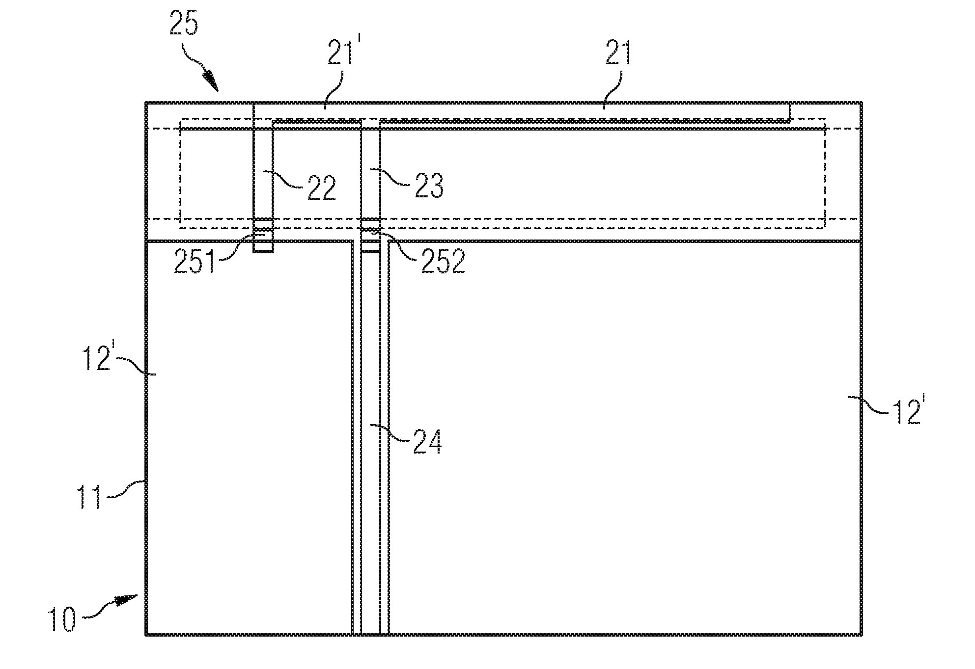
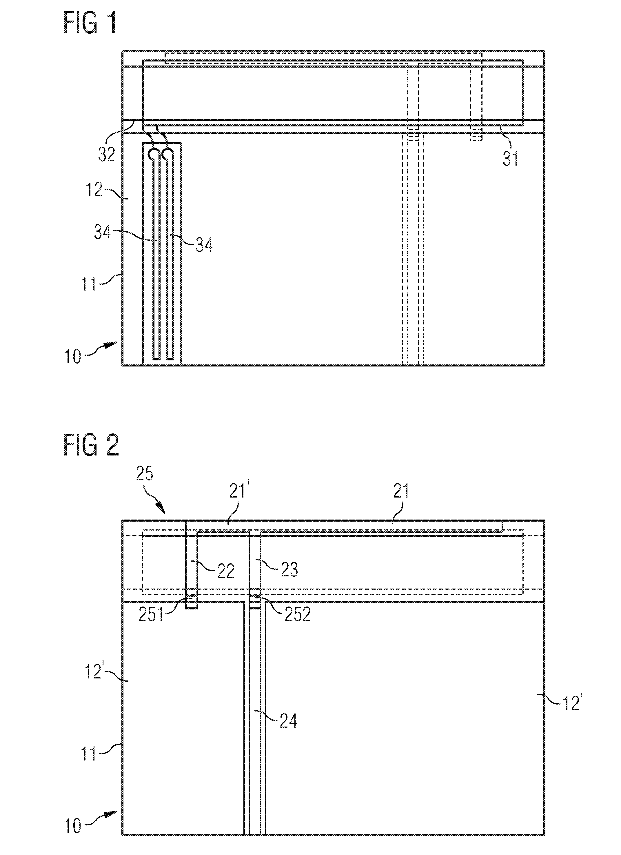
[0007]In one advantageous embodiment of the invention, a filter is arranged between the electric antenna and the magnetic antenna. This additional measure makes it possible to ensure that the two antennas are effectively isolated from each other.
[0008]According to a further advantageous embodiment of the invention, the filter is in the form of an LC high pass. Since the frequencies of the two antennas are generally very different from each other, this simple filter is enough to enable the antennas to be effectively isolated from each other. Where the electric antenna has an adapter loop, it is also particularly advantageous to use this adapter loop as an inductor for the LC high pass. This makes it possible to dispense with additional components. In a further advantageous embodiment, the filter is formed by virtue of the arrangement of a capacitor at each end of the adapter loop. This makes it possible to achieve particularly effective isolation of the electric antenna from the magnetic antenna.
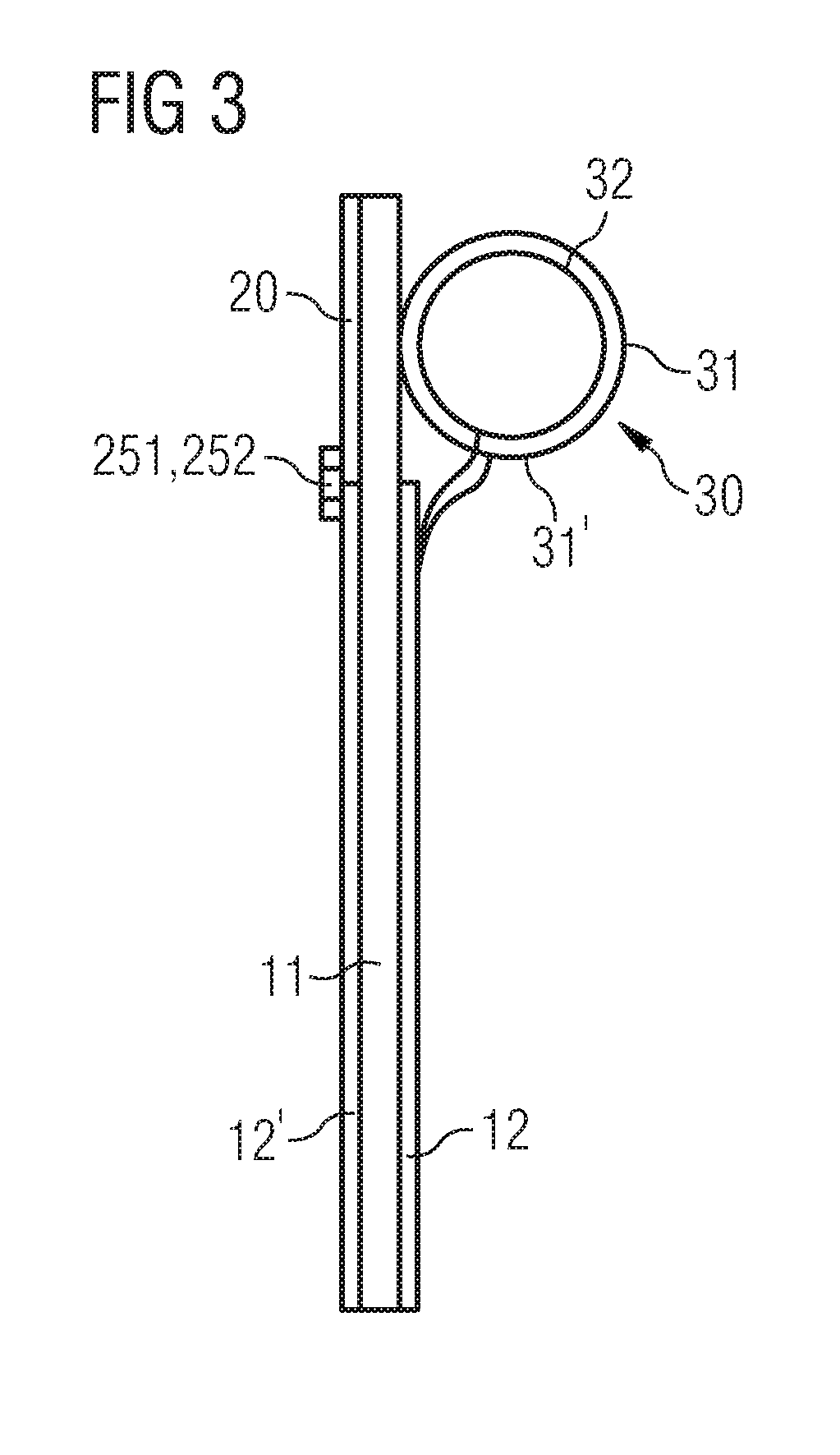
[0009]In a further advantageous embodiment of the invention, the magnetic antenna is in the form of a cylindrical coil with a ferromagnetic core, the ferromagnetic core being made from a material having a low electric conductivity and also having a low frequency-dependent relative permeability for the frequency of the electric antenna, such that field displacement of the electric antenna is avoided. The magnetic field of the coil is strengthened as a result of the use of the ferromagnetic core. The low electric conductivity of the coil core prevents eddy currents from being induced therein. Its low frequency-dependent relative permeability ensures that there is no disruptive field displacement of the electric antenna.
[0010]In a particularly advantageous embodiment of the invention, the antennas are arranged on opposite sides of a printed circuit board. Since, in this case, the two antennas use the same base area of the printed circuit board, a particularly space-saving antenna arrangement is thereby possible.
[0011]It is very advantageous for the electric antenna to be in the form of a printed conductor structure on the printed circuit board. An antenna of this kind can be very easily and inexpensively produced. Furthermore, this antenna requires a particularly small amount of space.
[0012]According to one advantageous embodiment of the invention, the electric antenna is in the form of a monopole antenna which is fed by an HF generator, the electric antenna having transformer adaptation to the line impedance of the HF generator. As a result of its design and its ease of adaptation to the line impedance, this “inverted F” antenna is well-suited to transmission procedures operating at frequencies of around 2.5 GHz. Since an inductor is already present in the form of a section of this antenna, it is particularly easy to produce a filter to isolate the antennas from each other.

Problems solved by technology

This involves the use of both magnetic and electric antennas, which are integrated into the hearing device, although it is difficult to integrate them into a hearing device owing to the confined space.
If, on the other hand, not just one but a plurality of antennas is to be integrated in a hearing device, for example one antenna for a short transmission range and one for a longer transmission range, integration becomes all the more difficult.
The reason is the added problem of arranging the antennas in the confined space in the hearing device housing such that there is as little mutual interference as possible.
This problem has not previously been satisfactorily solved.
Owing to the mutual interference of the two antennas they have to be spaced a minimum distance apart, however.
A relatively large amount of space is required to accommodate complex filters of this kind in hearing device housings.
The cost of manufacturing the hearing device is also thereby increased.

Method used


Image

  • Antenna arrangement for hearing device applications
  • Antenna arrangement for hearing device applications
  • Antenna arrangement for hearing device applications

Examples


Embodiment Construction

[0018]If electrical devices are to intercommunicate via a wireless transmission path, all the communicating peers have to be provided with a special interface. Apart from a transmission and reception circuit, each device must have an appropriate antenna designed for the particular transmission procedure.

[0019]An antenna is a special component that converts electrical energy into electromagnetic waves and vice versa. The way in which an antenna works and its characteristics (effective direction) are determined substantially by its design. This in turn depends primarily on the transmission procedure used and also on the frequencies used. In very simplified terms, an antenna consists of an electric conductor piece through which flows a high-frequency electric current. In the case of a transmitting antenna, the electric current is generated by a generator and fed to the antenna. The charge carriers moving in the conductor generate an electromagnetic field which changes direction at the ...


PUM


Abstract

A device having an electric antenna and a magnetic antenna is described, the antennas being spatially arranged in immediate mutual proximity. The electric antenna has at least one current-carrying electric conductor which acts as a resonator for the electric antenna, while the magnetic antenna has a coil with at least one current-carrying conductor loop which acts as an inductor of the magnetic antenna. Thus the electric antenna and the magnetic antenna are spatially arranged relative to each other such that the direction of the current in the electric conductor of the electric antenna extends substantially at right angles to the direction of the current in the conductor loop of the magnetic antenna.

Description

CROSS REFERENCE TO RELATED APPLICATIONS[0001]This application is the US National Stage of International Application No. PCT / EP2007 / 057745 filed Jul. 27, 2007 and claims the benefit thereof. The International Application claims the benefit of the U.S. provisional patent application filed on Jul. 28, 2006, and assigned application No. 60 / 834,310, both of the applications are incorporated by reference herein in their entirety.FIELD OF INVENTION[0002]The invention relates to an antenna arrangement in which a magnetic antenna for a short transmission range and an electric antenna for a longer transmission range are combined in a unit for hearing device applications such that there is no mutual interference.BACKGROUND OF INVENTION[0003]Hearing devices nowadays can be provided with special devices for wireless transmission for programming or interlinking purposes. This involves the use of both magnetic and electric antennas, which are integrated into the hearing device, although it is diff...

Claims


Application Information

Patent Timeline
Patent Type & Authority Applications(United States)
IPC IPC(8): H01Q7/08H01Q1/24H01Q21/00H01Q5/40
CPCH01Q1/273H01Q1/38H01Q1/521H01Q5/40H01Q9/42H04R25/554H04R2225/51H01Q7/06
Inventor SCHATZLE, ULRICH
Owner SIVANTOS PTE LTD
Why Eureka
Try Eureka