Self calibration methods for optical analysis system

a technology of optical analysis and self-calibration, which is applied in the direction of optical radiation measurement, instruments, spectrometry/spectrophotometry/monochromators, etc., can solve the problems of inability to accurately measure the data relating to one, inability to convert simple light intensity measurement to information, and inability to accurately estimate the accuracy of on

Active Publication Date: 2009-12-24
HALLIBURTON ENERGY SERVICES INC
View PDF103 Cites 77 Cited by
  • Summary
  • Abstract
  • Description
  • Claims
  • Application Information

AI Technical Summary

Problems solved by technology

In general, a simple measurement of light intensity is difficult to convert to information because it likely contains interfering data.
It is often impossible to adequately measure the data relating to one of these factors since the contribution of the other factors is unknown.
Depending on the circumstances, however, the estimate may be unacceptably inaccurate since factors other than ethylene may affect the intensity of the wavelength bands.
Unfortunately, however, charge couple devices and their required operational instrumentation are very expensive.
Furthermore, the devices are sensitive to environmental conditions.
The power requirements, cooling requirements, cost, complexity and maintenance requirements of these systems have made them impractical in many applications.
While various methodologies have been developed to enhance measurement accuracy in Optical Analysis Systems, no design has emerged that generally encompasses all of the desired characteristics as hereafter presented in accordance with the subject technology.

Method used


Image

  • Self calibration methods for optical analysis system
  • Self calibration methods for optical analysis system
  • Self calibration methods for optical analysis system

Examples


Embodiment Construction

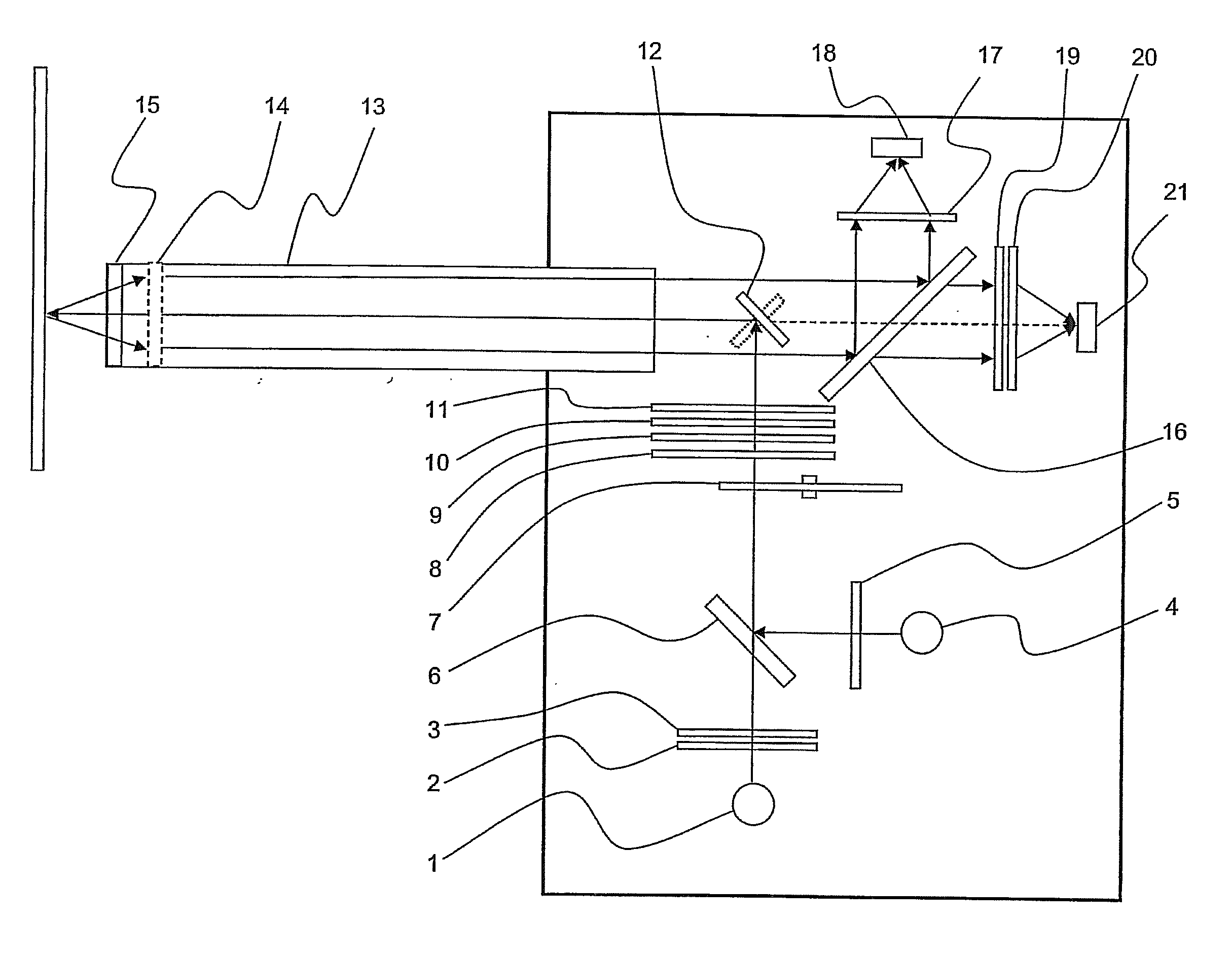
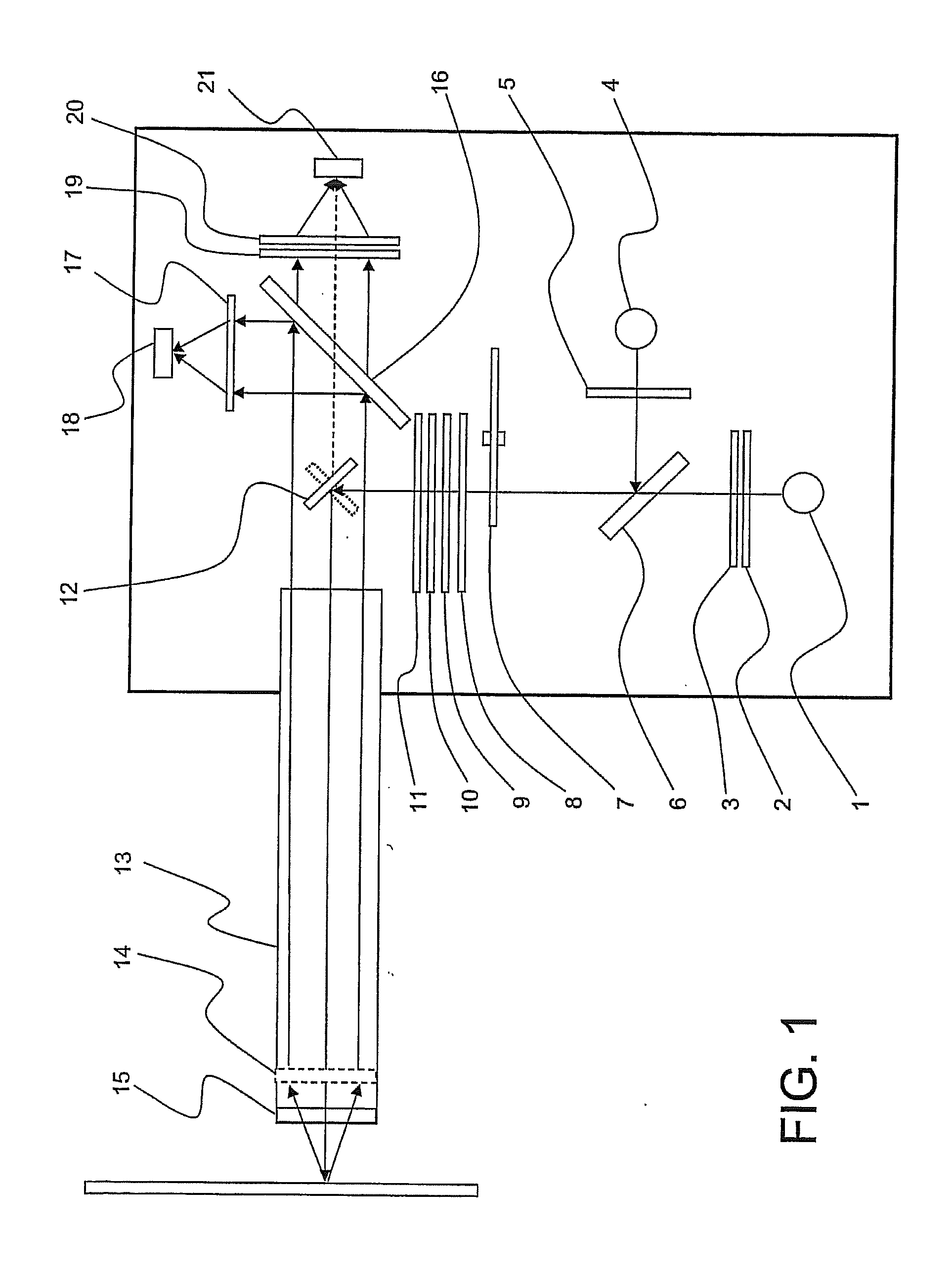
[0042]As discussed in the Summary of the Invention section, the present subject matter is particularly concerned with self calibration of optical analysis systems.

[0043]Selected combinations of aspects of the disclosed technology correspond to a plurality of different embodiments of the present invention. It should be noted that each of the exemplary embodiments presented and discussed herein should not insinuate limitations of the present subject matter. Features or steps illustrated or described as part of one embodiment may be used in combination with aspects of another embodiment to yield yet further embodiments. Additionally, certain features may be interchanged with similar devices or features not expressly mentioned which perform the same or similar function.

[0044]Reference will now be made in detail to the presently preferred embodiments of the subject self calibrating optical analysis system. Referring now to the drawings, FIG. 1 illustrates an optical analysis system in wh...


PUM

PropertyMeasurementUnit
opticalaaaaaaaaaa
optical analysisaaaaaaaaaa
displacementaaaaaaaaaa

Abstract

Disclosed is a system and methodologies for providing self-calibration in an optical analysis system. Illumination light is directed toward a material to be sampled while provisions are made to modify the characteristics of at least a portion of the illumination light falling on a reference detector. The modified characteristics may include light presence and / or spectral characteristics. Light presence may be modified by rotating or moving mirror assemblies to cause light to fall on either a sample detector or a reference detector while spectral characteristics may be modified by placing materials having known spectral characteristics in the path of the illumination light.

Description

CROSS-REFERENCE TO RELATED APPLICATIONS[0001]This application claims benefit of U.S. Provisional Patent Application Ser. No. 60 / 740,045, filed Nov. 28, 2005.FIELD OF THE INVENTION[0002]The present invention relates to spectroscopy analysis systems. More particularly, the invention relates to self-calibration apparatus and methodologies for use with multivariate optical computing systems.BACKGROUND OF THE INVENTION[0003]Light conveys information through data. When light interacts with matter, for example, it carries away information about the physical and chemical properties of the matter. A property of the light, for example, its intensity, may be measured and interpreted to provide information about the matter with which it interacted. That is, the data carried by the light through its intensity may be measured to derive information about the matter. Similarly, in optical communications systems, light data is manipulated to convey information over an optical transmission medium, fo...

Claims


Application Information

Patent Timeline
Patent Type & Authority Applications(United States)
IPC IPC(8): G01J3/28G01N21/27
CPCG01J3/02G01J3/0232G01J3/08G01N21/31G01J2003/1217G01N21/274G01J3/42
Inventor MYRICK, MICHAEL L.FREESE, ROBERT P.PERKINS, DAVID L.
Owner HALLIBURTON ENERGY SERVICES INC
Why Eureka
Try Eureka