
Image pickup apparatus

a pickup apparatus and image technology, applied in the field of image pickup apparatus, can solve the problems of high color reproducibility, high noise, and low cutoff characteristic of absorption type infrared cut filter, and achieve the effects of reducing noise, low cost, and low nois

Inactive Publication Date: 2006-01-10
OLYMPUS CORP
View PDF13 Cites 66 Cited by
  • Summary
  • Abstract
  • Description
  • Claims
  • Application Information

AI Technical Summary

Benefits of technology

[0029]A primary object of the present invention is to provide a composite infrared cut filter which has a high color reproducibility, produces little ghost and is capable of reducing noise as well as an image pickup apparatus which uses the filter.
[0035]The composite filter according to the present invention is composed by combining a reflection type filter and a transmission type filter which have different spectral characteristics, and has a spectral characteristic which can be modified relatively easily. Though it is conceivable to use only an absorption type filter and modify a spectral characteristic by changing its thickness, a spectral characteristic may be modified by changing a film configuration of a reflection type filter.

Problems solved by technology

Accordingly, the absorption type infrared cut filter is not always optimum for an image pickup apparatus which is restricted in a longitudinal direction, an endoscope or the like in particular.
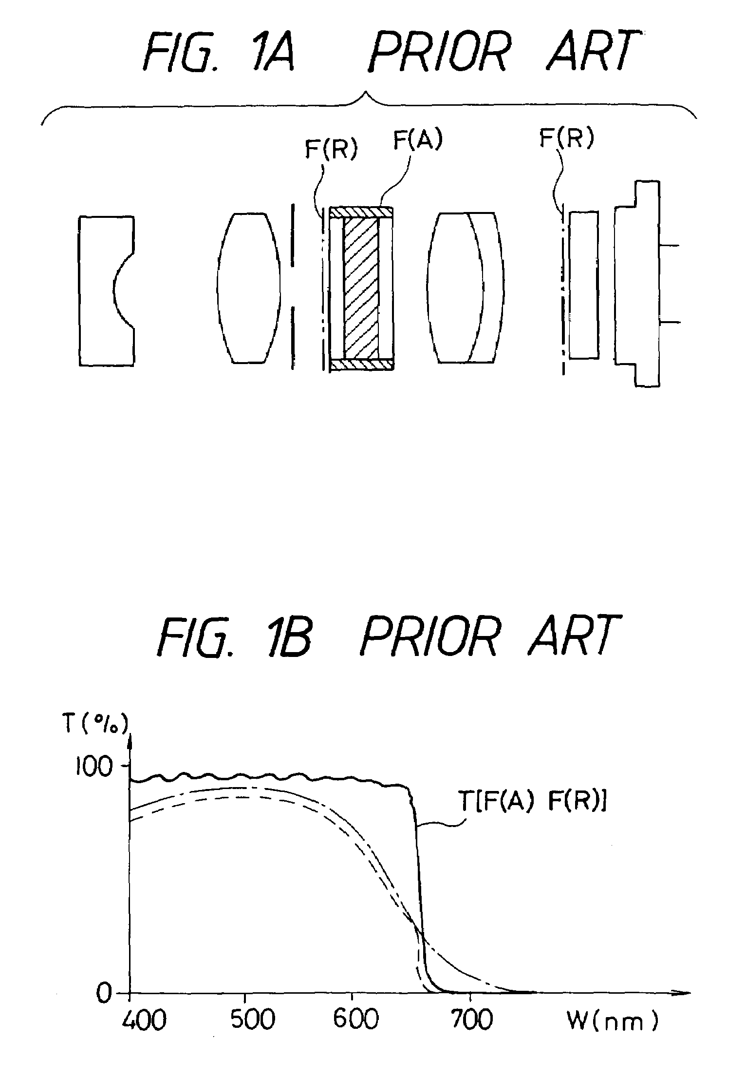
Furthermore, the absorption type infrared cut filter has a cutoff characteristic which traces a gentle curve and is not preferable from a viewpoint of a color reproducibility.
However, the reflection type filter has a highly reflective coated surface, and may produce flare and ghost.
However, it is actually impossible to obtain a function which is effective to satisfy a requirement described above simply by combining different kinds of filters as in the conventional example.
Furthermore, the utility model mentioned above makes no disclosure of a concrete filter which is effective to satisfy the requirement described above nor a characteristic of the filter.
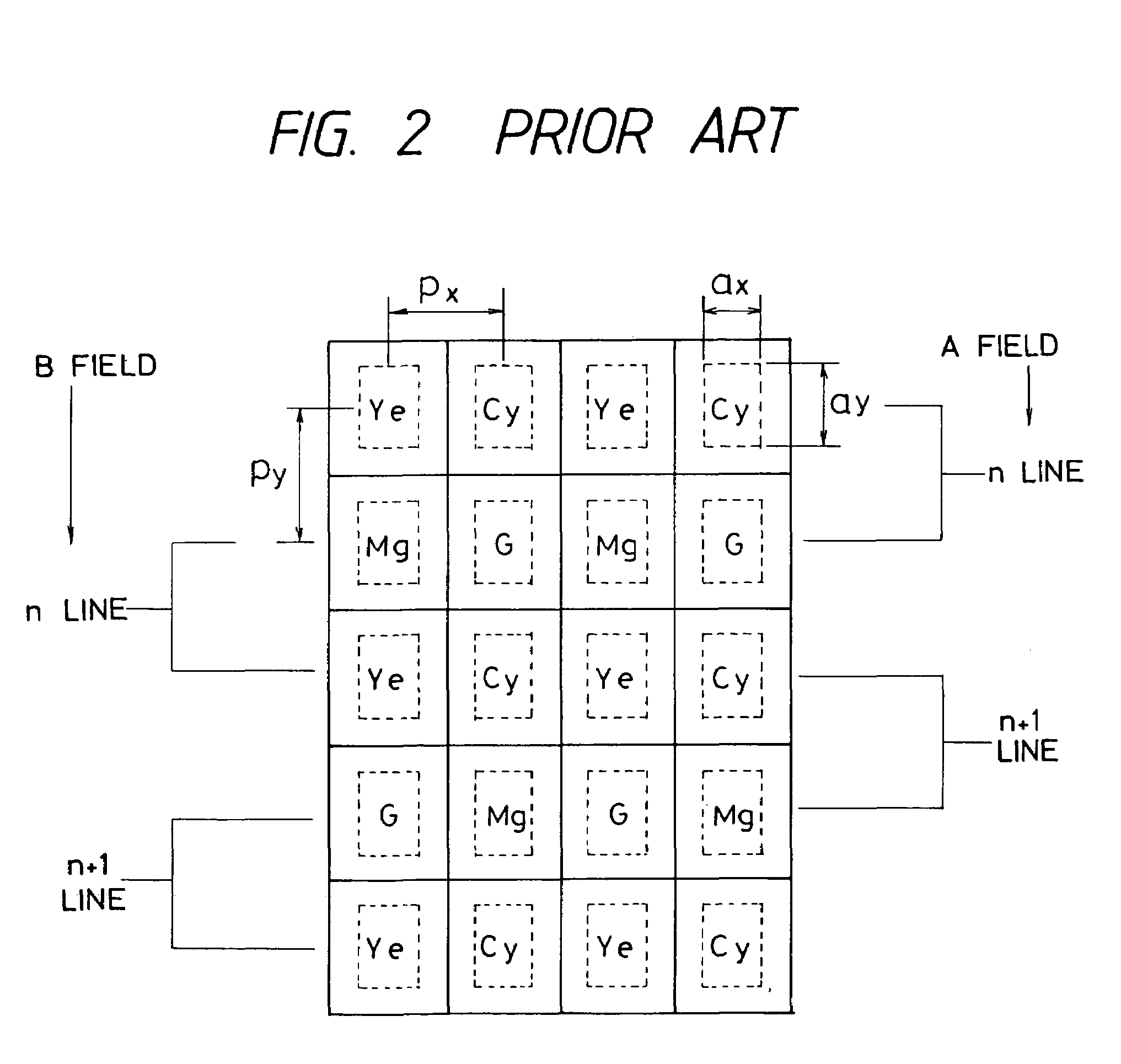
As a result, noise appears on a monitor as red light and shade.
Accordingly, the horizontal stripe noise is liable to be noticeable.
Furthermore, such an endoscope uses a light source which emits a light containing infrared spectral components in amounts relatively larger than those in natural light and fluorescent light, thereby inevitably requiring an infrared cut filter.
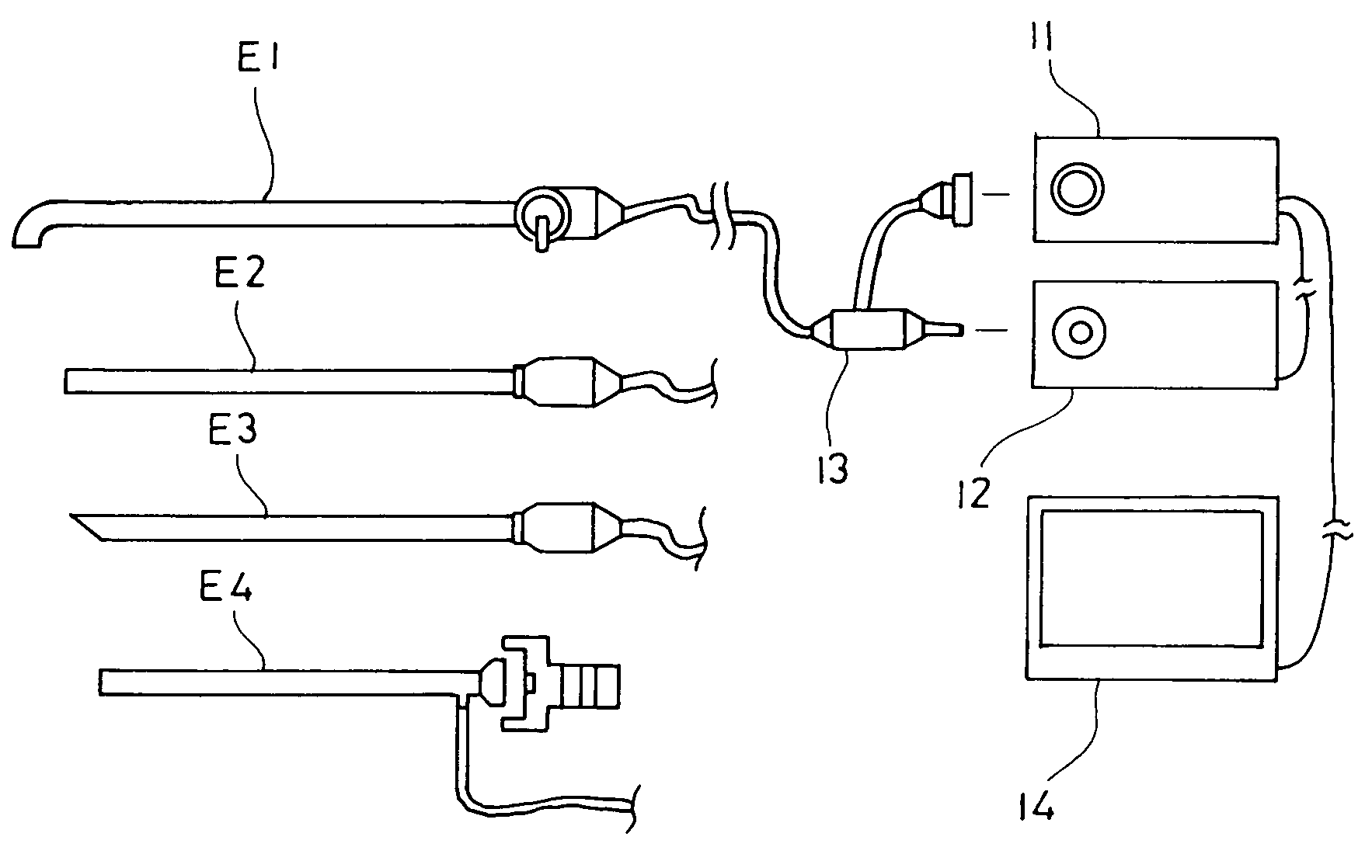
In case of an endoscope system which handles a plurality of endoscopes using different CCDs, it is naturally difficult to customize signal processing circuits which are specialized for individual fields or individual instruments.
Accordingly, a color reproducibility of the endoscope system is different dependently on endoscope used in the endoscope system and it may be difficult to correct this difference with the CCU.

Method used


Image

  • Image pickup apparatus
  • Image pickup apparatus
  • Image pickup apparatus

Examples


first embodiment

[0055]The image pickup system according to the present invention comprises a composite filter described below and the present invention is characterized by a composition of the composite filter. The composite filter is composed as shown in FIG. 3, wherein a reference symbol F1 represents an absorption type infrared cut filter and a reference symbol F2 designates a reflectin type cut coat formed on a surface of the absorption type infrared cut filter F1. The composite filter is composed by combining two kinds of filters as described above. FIG. 4 shows a total spectral transmittance characteristic of these filters combined with each other.

[0056]Examinations provided a result that a color reproducibility was enhanced but the noise like the horizontal stripes could not be suppressed to an unnoticeable level when only reflection type infrared cut filters were used. Furthermore, the reflection type infrared cut filters produced ghost peculiar thereto. The reflection type filters used for...

second embodiment

[0089]The second embodiment is a filter having a configuration which is suited for use not with a semiconductor laser but also a YAG laser.

[0090]The YAG laser has a wavelength region of approximately 1060 nm which cannot be cut off sufficiently with the composite filter preferred as the first embodiment. The second embodiment which comprises the additional reflection type filter F3 has a spectral characteristic illustrated in FIG. 6. As apparent from this drawing, the composite filter preferred as the second embodiment has transmittance of approximately 0 not only in the wavelength region of the semiconductor laser but also in the wavelength region of the YAG laser which is approximately 1060 nm. Taking into manufacturing of the filter into consideration, it is desirable to configure the YAG filter so as to have a cutoff frequency on the order of 1060±20 nm.

[0091]The following table lists transmittance of the filters shown in FIGS. 4 at various wavelengths:

[0092]

Transmittance T (%)W...

third embodiment

[0095]The objective optical system preferred as the third embodiment is a direct view type optical system which has a field angle of 131° and angle of 0° toward a visual field. Furthermore, a YAG ray cut coating F6 is formed on an object side surface of the absorption type filter (infrared cut filter) F4. Furthermore, the reflection type infrared cut filter F5 has a function to cut off the semiconductor laser rays.

[0096]When two or more kinds of reflection type filters are to be used as in the image pickup system preferred as the third embodiment, it is necessary to consider locations of the reflection type filters.

[0097]Since a spectral characteristic of a reflection type filter is influenced by an inclination angle of an incident ray, a location of the filter must be considered when the inclination is large.

[0098]The reflection type filters F4 and F4 used in the third embodiment are configured so that an angle of incidence θ(LD) of an offaxial ray incident on the absorption type i...


PUM


Abstract

An image pickup apparatus comprising an optical element which absorbs rays having specific wavelengths, an optical element which reflects rays having specific wavelengths and an organic color mosaic filter, wherein a total spectral characteristic of the optical elements satisfies the following condition:0.45≦|ΔT / ΔW|≦0.75.

Description

BACKGROUND OF THE INVENTION[0001]a) Field of the Invention[0002]The present invention relates to an image pickup apparatus, and more specifically an image pickup apparatus which uses a composite filter.[0003]b) Description of the Prior Art[0004]It is general to use an infrared cut filter in combination with a single plate color CCD in order to cut detrimental near infrared rays.[0005]Known as infrared cut filters are an absorption type filter which absorbs rays having specific wavelengths dependently on concentrations of pigments and a reflection type filter using an interference film which cancels only rays having specific wavelengths by utilizing a phase difference.[0006]Out of these infrared cut filters, the absorption type infrared cut filter must have a certain definite thickness to obtain a specific spectral characteristic dependently on the concentrations of the pigment. Accordingly, the absorption type infrared cut filter is not always optimum for an image pickup apparatus w...

Claims


Application Information

Patent Timeline
IPC IPC(8): H04N13/00A61B1/06H04N7/18A61B1/04G02B5/20G02B5/22G02B23/24H04N5/225H04N9/04
CPCA61B1/00163A61B1/042G02B23/243H04N9/045G02B5/223H04N2005/2255H04N23/555H04N25/136
Inventor TSUYUKI, HIROSHI
Owner OLYMPUS CORP
Learn More