Mode-locked solid-state laser apparatus

a laser apparatus and mode lock technology, applied in the direction of laser details, instruments, optical resonator shape and construction, etc., can solve the problems of difficult stably operating solid-state laser apparatuses containing one-meter class resonators, undesirable q-switched mode locking applications, etc., to achieve stable soliton-mode oscillation and operation. stab

Inactive Publication Date: 2009-12-24
FUJIFILM CORP
View PDF3 Cites 4 Cited by
  • Summary
  • Abstract
  • Description
  • Claims
  • Application Information

AI Technical Summary

Benefits of technology

[0072]On the other hand, in the mode-locked solid-state laser apparatus in which the SESAM is arranged in close vicinity to or in contact with the laser medium, pulses competing with the soliton pulses preferentially acquire the gain because of the spatial hole burning. (That is, the gain advantage of the pulses competing with the soliton pulses over the soliton pulses increases.) Therefore, there is a fear that the soliton pulses cannot be stably generated. The present inventors have found that stable soliton-mode oscillation can be realized by setting the depth of absorbing modulation at the saturable absorbing mirror to a value equal to or greater than 0.4%, and setting the total intracavity dispersion D to a value realizing such a pulse bandwidth that the saturable absorbing mirror can suppress the pulses comp

Problems solved by technology

However, generally, the Q-switched mode locking is undesirable in the applications other than the energetic use because of the instability in the output, pulse width, and pulse period.
That is, the size of the solid-state laser apparatus becomes large.
However, generally, solid-state laser apparatuses containing a one-meter class resonator are hard to stably operate.
Therefore, the stability of the laser oscillation in the conventional solid-state laser apparatuses is low.
In addition, since the conventional solid-state laser apparatuses are constituted by a great number of optical components, the cost of the conventional solid-state laser apparatuses is high.
However, the conventional techniques explained above have the following problems.
That is, almost no output light can be outputted through such an output mirror.
Therefore, the dielectric multilayer film disclosed in JP2000-138407A does not have a sufficient function of an output mirror.
Therefore, it is difficult to achieve satisfactory downsizing and stabilization of the solid-state laser apparatus.
The Pas

Method used


Image

  • Mode-locked solid-state laser apparatus
  • Mode-locked solid-state laser apparatus
  • Mode-locked solid-state laser apparatus

Examples


Embodiment Construction

[0114]Embodiments of the present invention are explained in detail below with reference to drawings.

1. Apparatus Configuration (FIG. 1)

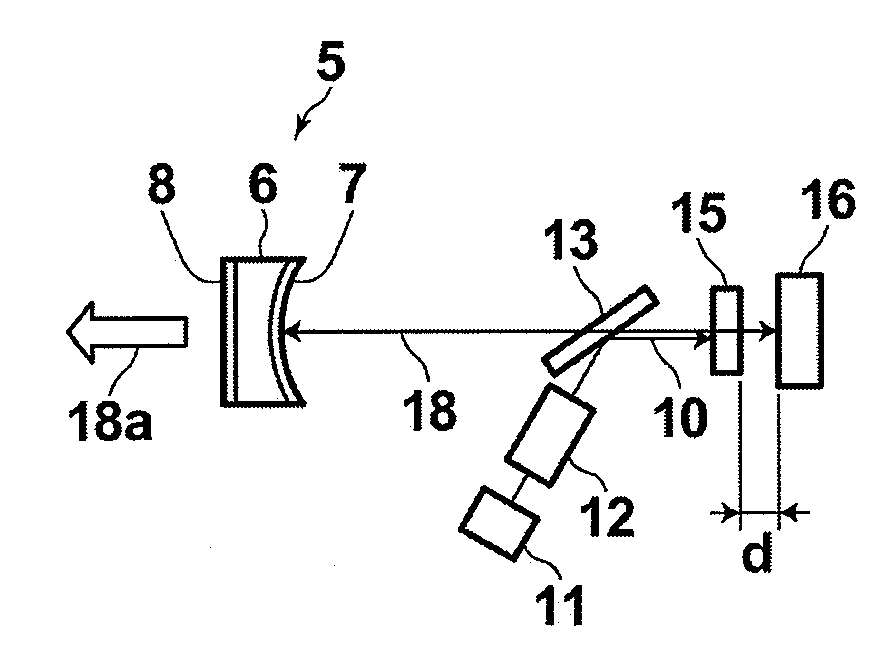
[0115]FIG. 1 is a schematic side view illustrating an exemplary configuration of a soliton mode-locked solid-state laser apparatus according to an embodiment of the present invention. The mode-locked solid-state laser apparatus of FIG. 1 comprises a semiconductor laser 11, an excitation optical system 12, a dichroic mirror 13, a negative-dispersion mirror 5, a semiconductor saturable absorbing mirror (SESAM) 16, and a solid-state laser medium 15. The semiconductor laser 11 emits excitation light (pumping light) 10. The excitation optical system 12 externally injects the excitation light 10 into a resonator in the mode-locked solid-state laser apparatus of FIG. 1 along a direction nonparallel to the optical axis of the resonator. The dichroic mirror 13 is arranged in the resonator, and reflects the excitation light 10 toward the solid-state laser medi...


PUM


Abstract

In a mode-locked laser-diode-excited laser apparatus: a solid-state laser medium is arranged at a distance of at most twice the Rayleigh range from a saturable absorbing mirror with a depth of absorbing modulation of at least 0.4%; the total intracavity dispersion is smaller than zero and makes oscillating light have such a pulse bandwidth that the saturable absorbing mirror can suppress a background pulses other than soliton pulses repeated with a fundamental repetition period, and the magnitude of the total intracavity dispersion has a predetermined relationship with a pulse width of the oscillating light; and an output mirror is a negative-dispersion mirror being constituted by three or more multilayer mirrors and cavity layers arranged at predetermined intervals between the three or more multilayer mirrors, and causing a mirror dispersion of −3000 fsec2 to −600 fsec2 and realizes a reflectance of 97% to 99.5%.

Description

BACKGROUND OF THE INVENTION[0001]1. Field of the Invention[0002]The present invention relates to a solid-state laser apparatus, and in particular to a small-sized, mode-locked solid-state laser apparatus which has high output power, and enables highly efficient, short-pulse generation.[0003]2. Description of the Related Art[0004]Conventionally, efforts of developing solid-state lasers in which a solid-state laser medium (e.g., a laser crystal, ceramic substance, glass, or the like) doped with rare-earth ions or transition-metal ions is excited with a semiconductor laser (laser diode (LD)) as an excitation light source have been actively made. Among others, a wide variety of applications of the short-pulse lasers, which emit the so-called short light pulses (having the durations on the order of picoseconds to femtoseconds), have been searched for and proposed, and part of such applications have been put into practical use after verification.[0005]In the short-pulse lasers, the short ...

Claims


Application Information

Patent Timeline
IPC IPC(8): H01S3/098
CPCG02B5/0833H01S3/08H01S3/08059H01S3/0815H01S2301/085H01S3/1118H01S3/1618H01S3/1675H01S3/09415
Inventor KASAMATSU, TADASHIYAMAZOE, SHOGOUSUI, MAKIO
Owner FUJIFILM CORP
Why Eureka
Try Eureka