Decelerating Device and Projection Screen Rolling Mechanism

a technology of projection screen and rolling mechanism, which is applied in the direction of gearing details, gearing, instruments, etc., can solve the problems of easy damage of projection screen, very fast rotational speed of rotation shaft,

Active Publication Date: 2009-12-24
AIXIN TECH
View PDF0 Cites 20 Cited by
  • Summary
  • Abstract
  • Description
  • Claims
  • Application Information

AI Technical Summary

Benefits of technology

[0014]In view of the mentioned above, when the tube rotates above the specific rotational speed along the second rotational direction, each of the first balls affected by a centrifugal force is exposed outside the outer surface of th

Problems solved by technology

However, in the conventional art, the rotational speed of rotation s

Method used


Image

  • Decelerating Device and Projection Screen Rolling Mechanism
  • Decelerating Device and Projection Screen Rolling Mechanism
  • Decelerating Device and Projection Screen Rolling Mechanism

Examples


first embodiment

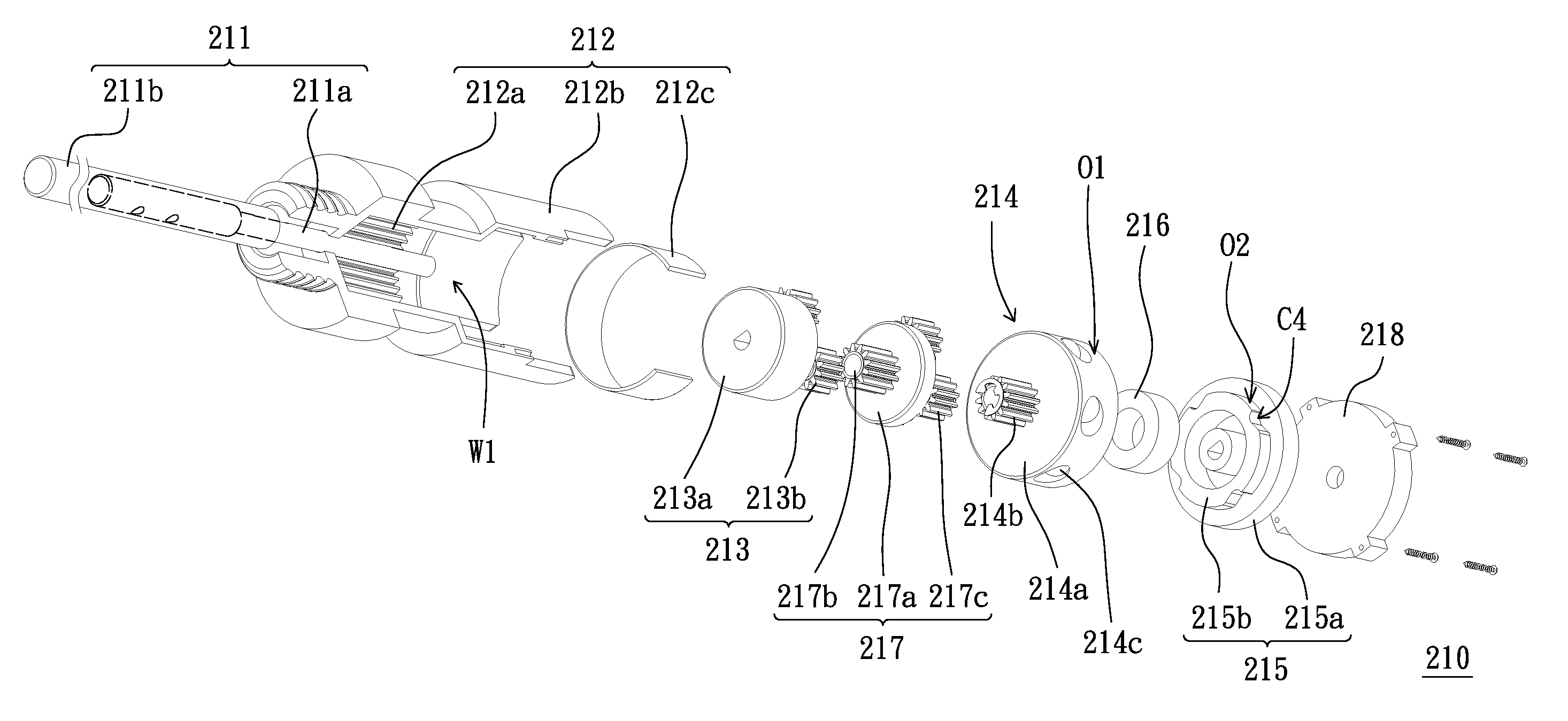
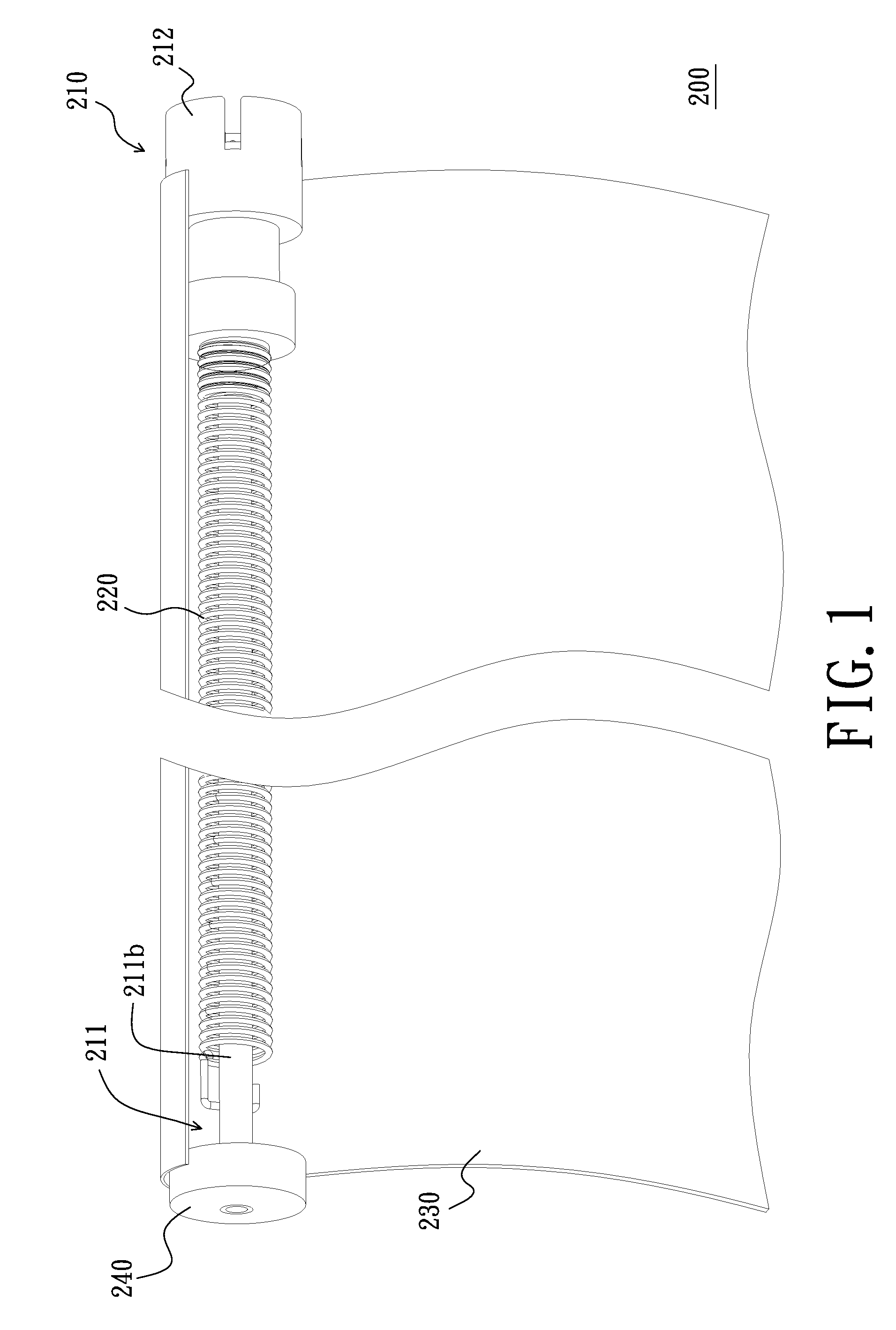
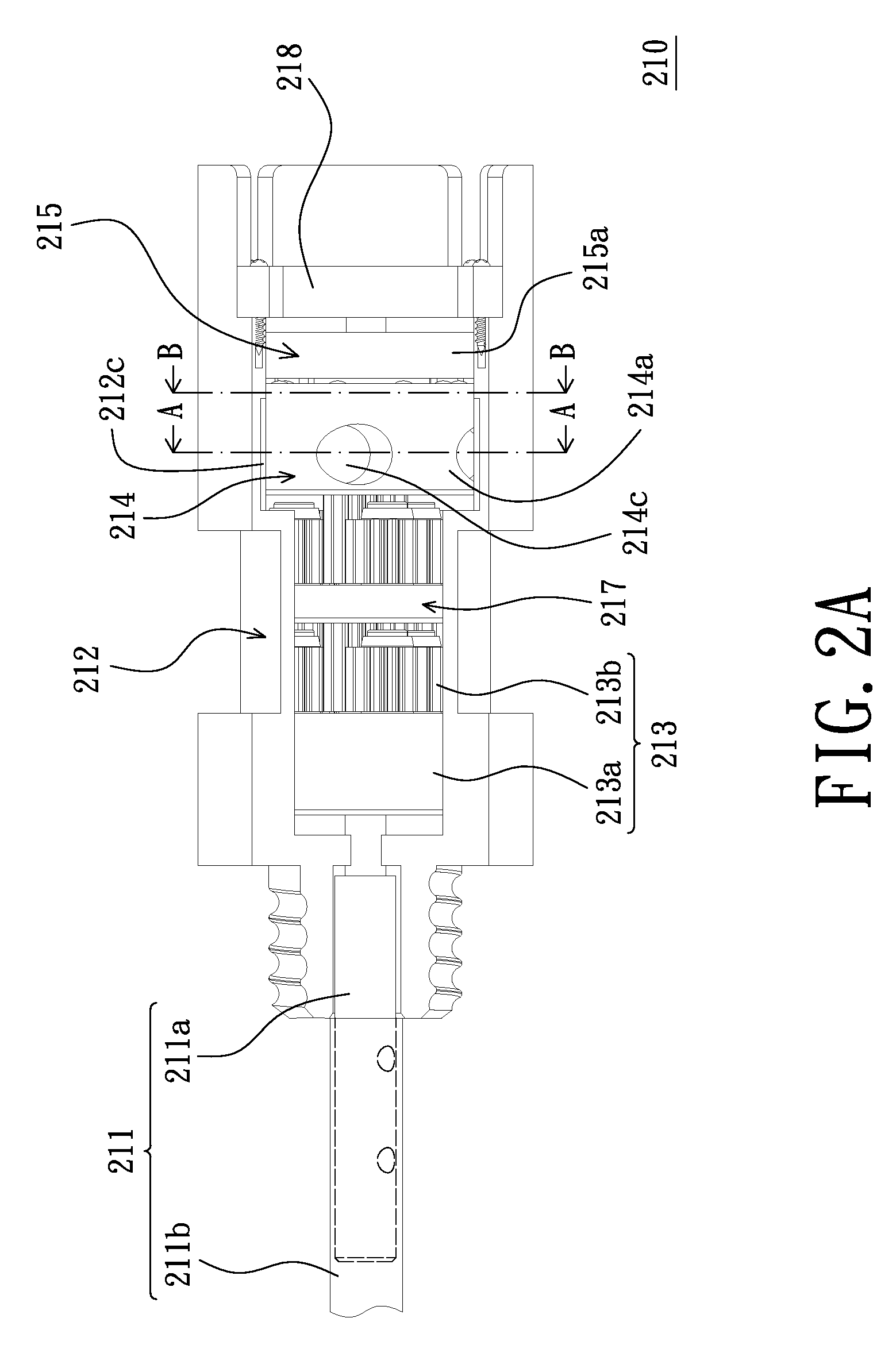
[0037]FIG. 1 is a schematic view of a projection screen rolling mechanism in the first embodiment of the present invention. FIG. 2A is a schematic view of the decelerating device in FIG. 1. FIG. 2B is a schematic exploded view of the decelerating device in FIG. 2A. FIG. 2C is another schematic exploded view of the decelerating device in FIG. 2A. FIG. 3A is a schematic cross-sectional view of the decelerating device in FIG. 2A along the line A-A. FIG. 3B is a schematic cross-sectional view of the decelerating device in FIG. 2A along the line B-B. It should be noted that a cutaway view of the tube (see the following description) is illustrated in FIGS. 2A, 2B and 2C for convenient illustration.

[0038]Please referring to FIGS. 1 and 2A, a projection screen rolling mechanism 200 in the present embodiment includes a decelerating device 210, a torsional spring 220, a projection screen 230 and an auxiliary rotation wheel 240. The decelerating device 210 includes a fixed shaft 211, a tube 21...

second embodiment

[0053]FIG. 8A is a schematic view of the decelerating device in the second embodiment of the present invention. FIG. 8B is a schematic exploded view of the decelerating device in FIG. 8A. FIG. 8C is another schematic exploded view of the decelerating device in FIG. 8A. FIG. 9 is a schematic cross-sectional view of the decelerating device in FIG. 8A along the line C-C.

[0054]Please referring to FIGS. 8A, 8B and 8C, the shape of a fixed element 315 of a decelerating device 310 is different from that of the fixed element 215 of the decelerating device 210 (see FIG. 2B). The outer ring 214d (see FIG. 2C) and the second balls 214e (see FIG. 2C) is removed from the decelerating device 310.

[0055]Please referring to FIGS. 8A, 8B, 8C and 9, the fixed element 315 of the decelerating device 310 is fixed at a fixed shaft 311 and located in a wheel 314a of a driven element 314. Each of the holes H11 has a first cavity C11 and a second cavity C21. The fixed element 315 has at least one third cavit...


PUM


Abstract

A decelerating device includes a fixed shaft, a tube, a transmission element and a driven element is provided. The tube is disposed around the fixed shaft and adapted to rotate about the fixed shaft. The transmission element has a fixed portion fixed at the fixed shaft and a planetary gear revolvably disposed at the fixed portion. The teeth of the tube are geared to the planetary gear. The driven element has a wheel, a sun gear fixed at the wheel and a plurality of balls. The sun gear and the wheel are revolvably disposed at the fixed shaft and in the tube. The planetary gear is adapted to drive the sun gear. The wheel has holes. Each of the holes extends from an outer surface of the wheel facing the tube to the interior of the wheel to form a cavity. The balls are disposed in the holes respectively.

Description

BACKGROUND[0001]1. Field of the Invention[0002]The present invention relates to a decelerating device. More particularly, the present invention relates to a projection screen rolling mechanism comprising the decelerating device.[0003]2. Detailed Description of the Related Art[0004]A present optical projector, such as a single beam projector and an LCD projector, may project images with high definition and high brightness. In addition, the optical projector has the advantages of lower price which is similar to that of the conventional TV sets, small volume, and easy to carry. Accordingly, the optical projector is increasingly accepted by most people in the society.[0005]On a large occasion for speech, the optical projector projects images on a projection screen such that the audience looks at the information on the projection screen easily. In the conventional art, the projection screen and a rolling unit together compose a projection screen rolling mechanism. One side of the project...

Claims


Application Information

Patent Timeline
IPC IPC(8): F16H57/10G03B21/58
CPCG03B21/58
Inventor YANG, XIN-CHANG
Owner AIXIN TECH
Why Eureka
Try Eureka