Parallel flow meter device for measuring flow rate in pipes

Inactive Publication Date: 2009-12-31
SAMANI ZOHRAB A
View PDF7 Cites 7 Cited by
  • Summary
  • Abstract
  • Description
  • Claims
  • Application Information

AI Technical Summary

Benefits of technology

[0007]The invention eliminates the disadvantages of measuring flow rate through a first pipe by using a small flow meter on a small by-pass pipe. The flow in the first pipe partitions between the first pipe and the by-pass second pipe. The partitioning of the flow is based on two principles of fluid mechanics; the conservation of energy and the conservation of mass. The principles of fluid mechanics is then used to relate the flow rate of the by-pass pipe to the combined flow rate through the first pipe and the by-pass second pipe.
[0008]The

Problems solved by technology

The flow meters are expensive.
The cost of flow meters increases as the flow rate or pipe size increases.
The flow meter also acts like an

Method used


Image

  • Parallel flow meter device for measuring flow rate in pipes
  • Parallel flow meter device for measuring flow rate in pipes
  • Parallel flow meter device for measuring flow rate in pipes

Examples


Embodiment Construction

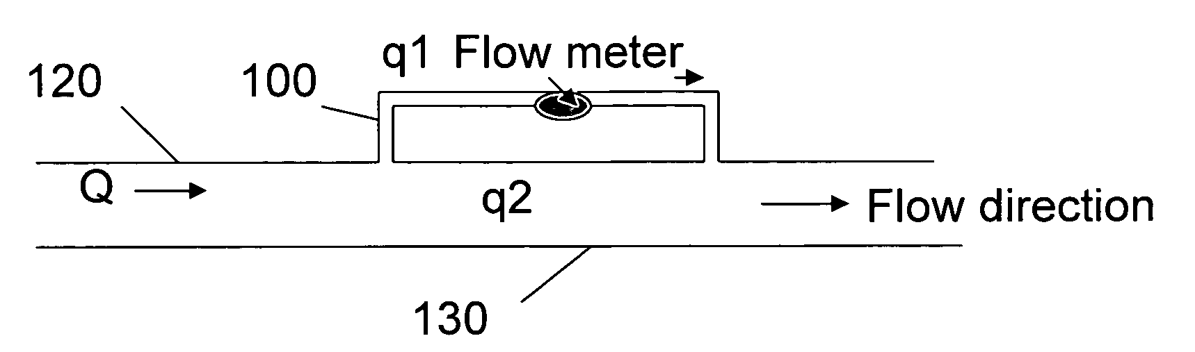
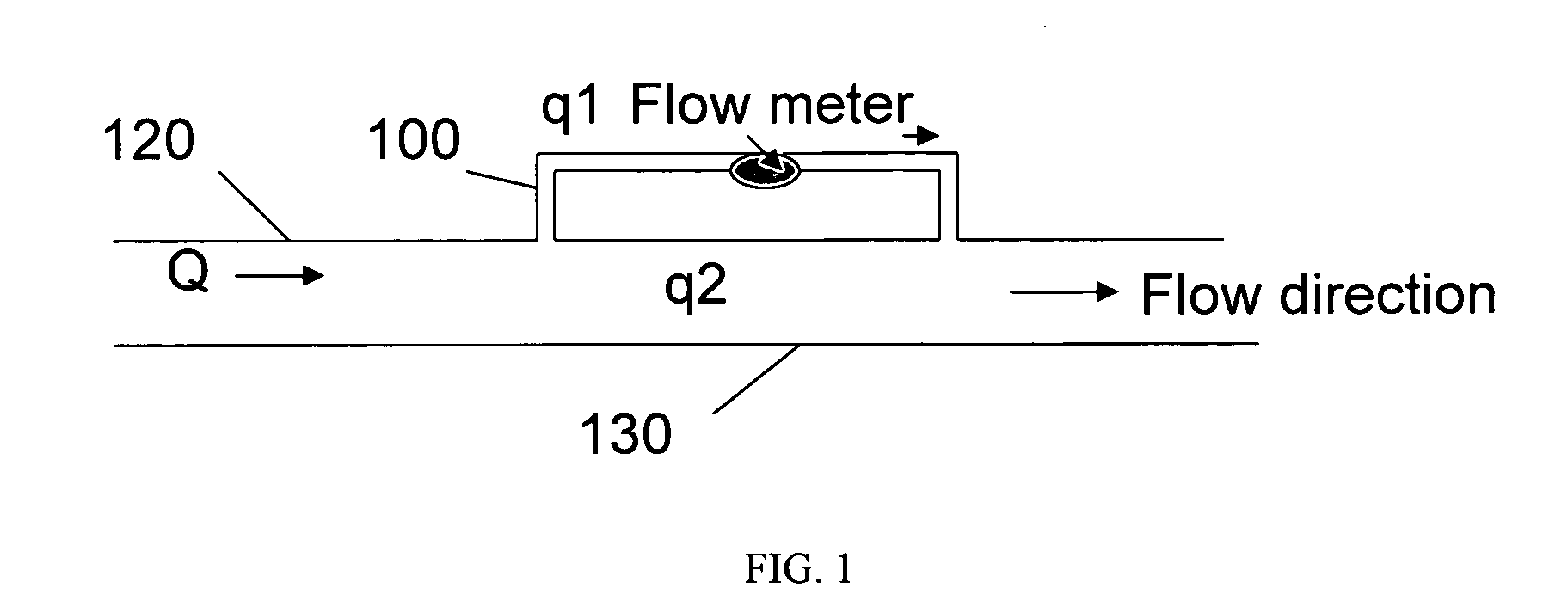
[0012]The present invention provides a system and method for measuring flow rate in pipes. The embodiment of the present invention consist of a system of parallel pipes where the flow of liquid or gas is partitioned between parallel pipes as shown in FIG. 1.

The invention provides a way of measuring flow rate at lower cost.

[0013]As used in the specification and claims herein, the terms “a”, “an”, and “the” means one or more. The term “liquid” means continuous amorphous substance that tends to flow and to conform to the outline of its container, such as water, petroleum or any other liquid. The term gas refers to a state of the matter, consisting of a collection of particles (molecules, ions, electrons, etc.) without a definite shape or volume that are in more or less random motion, such as air.

[0014]Traditionally, flow rates of liquid or gas flowing through a pipe such as water flowing out of a pump, is measured by installing a flow meter inside the pipe. Propeller meter is a commonl...


PUM


Abstract

The present invention relates to methods and apparatuses for measuring flow rate in pipes. The standard method of installing flow meters inside pipes to measure flow rates are costly and result in loss of energy and reduction of flow. The present invention solves the problems of standard flow measuring method. The present invention uses an apparatuses comprising of a first pipe and a by-pass second pipe. The flow is partitioned between the first pipe and the by-pass second pipe. A flow meter is installed in the by-pass second pipe. The flow rate is measured through the by-pass second pipe, and using the by-pass second pipe flow rate, the combined flow rate through the first pipe and the by-pass second pipe is calculated. The invention describes two methods to calibrate the apparatuses and relate the flow rate in the by-pass second pipe to total combined flow rate.

Description

[0001]This application claims priority to U.S. Provisional Patent Application Ser. No. 61 / 132,492 entitled “Description of a Parallel Flow Meter Device to Measure Liquid or Gas Flow in Pipes,” filed on Jun. 19, 2008, and the specification of that application is incorporated herein by reference. This is a substitute specification and contains no new matter.BACKGROUND OF INVENTION[0002]Field of Invention (Technical Field)[0003]The present invention relates to method and apparatuses for measuring flow rates of liquid or gas in pipes, resulting in lower equipment cost and lower energy cost.BRIEF SUMMARY OF THE INVENTION[0004]The present invention relates to an apparatus and method of measuring flow rate in pipes. The embodiment is described below.[0005]Traditionally, flow rates of liquid or gas flowing through a pipe is measured by installing a flow meter inside the pipe. The flow meter measures the flow rate and total cumulative flow passing through the pipe. This method of flow measur...

Claims


Application Information

Patent Timeline
IPC IPC(8): G01F15/02G01F25/00
CPCG01F25/0007G01F5/00G01F25/10
Inventor SAMANI, ZOHRAB A.
Owner SAMANI ZOHRAB A
Why Eureka
Try Eureka