Parametric amplification of a MEMS gyroscope by capacitance modulation

a capacitance modulation and gyroscope technology, applied in the field of microelectromechanical systems (mems) gyroscope sensors, can solve the problems of quadrature-phase signal producing errors in coriolis-phase signals, very limited bandwidth of such sensors, and stability issues

a capacitance modulation and gyroscope technology, applied in the field of microelectromechanical systems (mems) gyroscope sensors, can solve the problems of quadrature-phase signal producing errors in coriolis-phase signals, very limited bandwidth of such sensors, and stability issues

US20090320591A1Active Publication Date: 2009-12-31HONEYWELL INT INC

Image

  • Parametric amplification of a MEMS gyroscope by capacitance modulation
  • Parametric amplification of a MEMS gyroscope by capacitance modulation
  • Parametric amplification of a MEMS gyroscope by capacitance modulation

Examples


Embodiment Construction

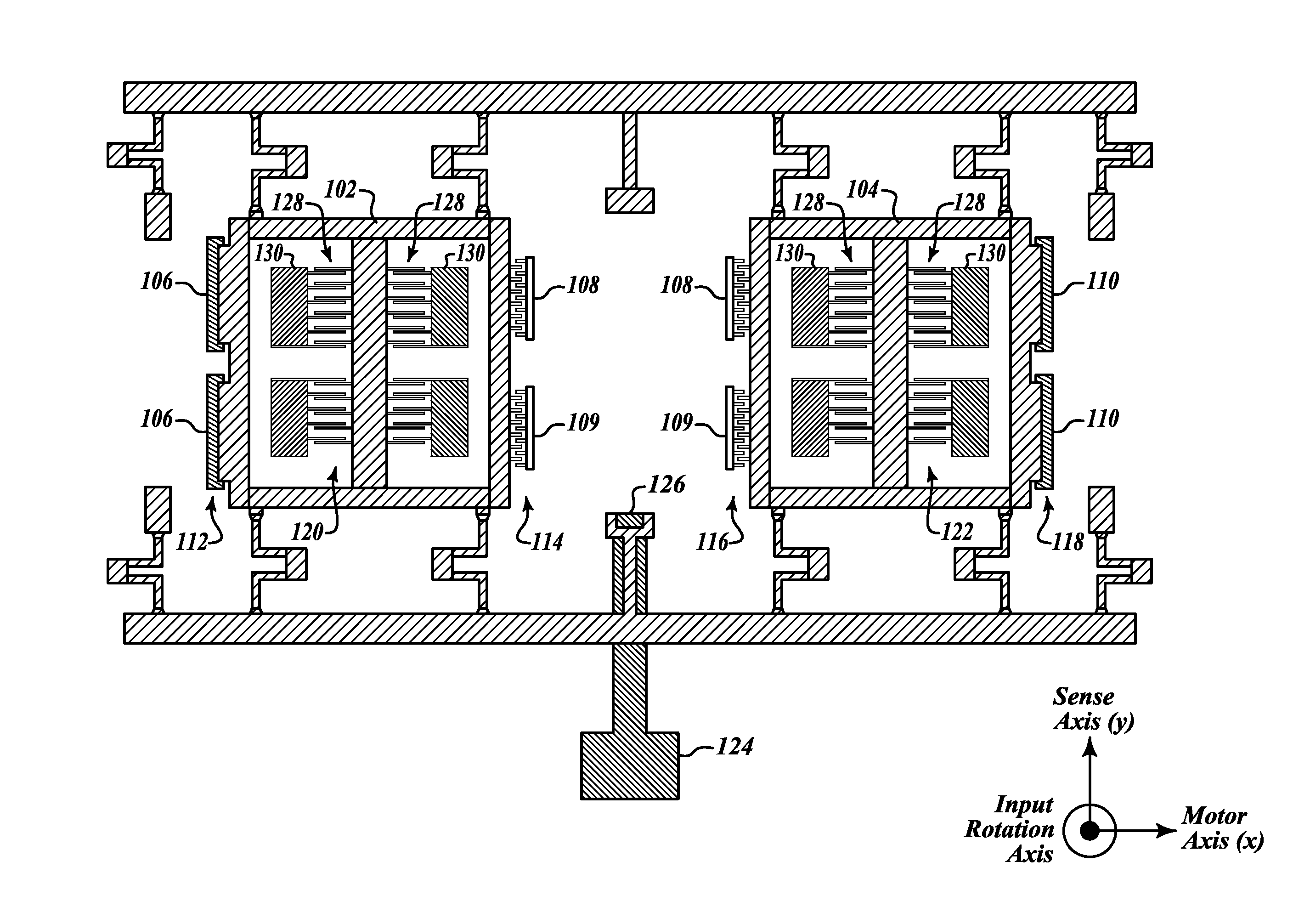
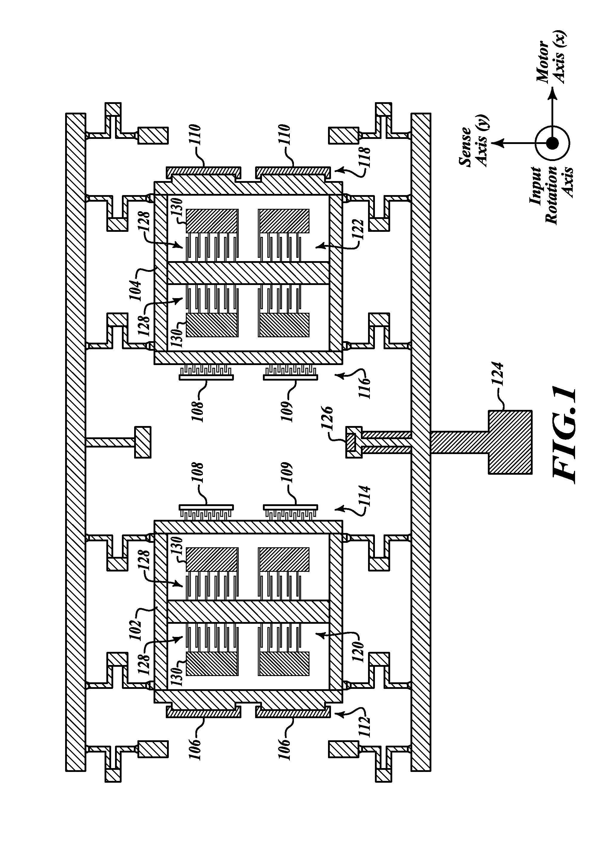
[0019]FIG. 1 illustrates an exemplary Micro-Electro-Mechanical Systems (MEMS) capacitance modulation device 100. The exemplary embodiment of the MEMS capacitance modulation device 100 has a first vibrating mass 102, a second vibrating mass 104, one or more left motors 106, a top center motor pickoff 108, a bottom center motor pickoff 109, one or more right motors 110, a left comb structure 112, a first center comb structure 114, a second center comb structure 116, a right comb structure 118, left sense electrodes 120, right sense electrodes 122, and an output electrode 124 coupled to one or more anchor points 126.

[0020]The left motor 106 is capacitively coupled to the first vibrating mass 102 via the left comb structure 112. The right motor 110 is capacitively coupled to the second vibrating mass 104 via the right comb structure 118. The center motor pickoffs 108, 109 are capacitively coupled to the first vibrating mass 102 via the first center comb structure 114. The center motor p...


PUM


Abstract

Parametric amplification of the output of a MEMS gyroscope is achieved by modulating the sense capacitance, or an auxiliary capacitance having an applied DC voltage. The capacitance modulation is produced by the driven motion of the gyroscope mechanism, so the pump signal of the parametric amplifier is not subject to phase errors in the electronics. The capacitance modulation affects the mechanical gain of the sensor (transfer function from input force to sensor mechanism displacement), as well as the electrical gain of the sensor (transfer function from sensor mechanism displacement to output electrical signal). The mechanical and electrical gains of the sensor become phase-dependent, so the Coriolis rate signal can be amplified while the unwanted quadrature-phase signal is attenuated.

Description

PRIORITY CLAIM[0001]This patent application claims priority from copending U.S. Provisional Patent Application Ser. No. 61 / 013,041 filed Dec. 12, 2007, and entitled, “Parametric Amplification of a MEMS Gyroscope by Capacitance Modulation,” the contents of which are hereby incorporated by reference in its entirety.GOVERNMENT INTEREST[0002]The present invention was made with support from the United States Government under contract number W15P7T-05-C-P609 and / or W15P7T-07-C-P609 awarded by the United States Army. The United States Government may have certain rights in the invention.BACKGROUND OF THE INVENTION[0003]A Micro-Electro-Mechanical Systems (MEMS) gyroscope sensor consists of one or more movable proof masses connected to each other and to one or more substrates by flexible suspensions. Typically, the proof masses and suspensions are fabricated by etching heavily doped silicon, and the silicon is bonded to one or more upper and / or lower glass or silicon substrates.[0004]The proo...

Claims


Application Information

Patent Timeline
31 Dec 2009
Publication
US20090320591A1
IPC
G01C19/56
CPC
G01C19/5719; G01C19/5726
Inventors
JOHNSON, BURGESS R.