Engine-driven power generator apparatus

a generator and engine technology, applied in the direction of engine cooling apparatus, coolant flow control, machines/engines, etc., can solve the problems of increasing the number of necessary components, increasing the weight of the engine-driven power generator apparatus, and increasing the air suction and exhaust sound (or noise), so as to effectively suppress the air suction and exhaust sound of the engine, and reducing the temperature of the case without affecting its mobility and portability

Active Publication Date: 2009-12-31
HONDA MOTOR CO LTD
View PDF5 Cites 13 Cited by
  • Summary
  • Abstract
  • Description
  • Claims
  • Application Information

AI Technical Summary

Benefits of technology

[0011]In view of the foregoing prior art problems, it is an object of the present invention to provide an improved engine-driven power generator apparatus wh

Problems solved by technology

Further, as the displacement of the engine increases, air suction and exhaust sound (or noise) increases.
However, providing the sound absorbing material on the inner surface of the case would increase the number of necessary component parts and thus increase the weight of the engine-driven power generator apparatus.
Further, because providing the sound absorbing material on the inner surface of the case requires an extra space therefor within the case, the size of the engine-driven power generator apparatus would increase.
Consequently, it has heretofore been difficult to reduce the weight and size of the engine-driven power generator apparatus.
In addition, the increased weight and size of the engine-driven power generator apparatus would impair the mobility and portability of the engine-driven power generator apparatus.
Furthermore, with the engine-driven power generator ap

Method used


Image

  • Engine-driven power generator apparatus
  • Engine-driven power generator apparatus
  • Engine-driven power generator apparatus

Examples


Embodiment Construction

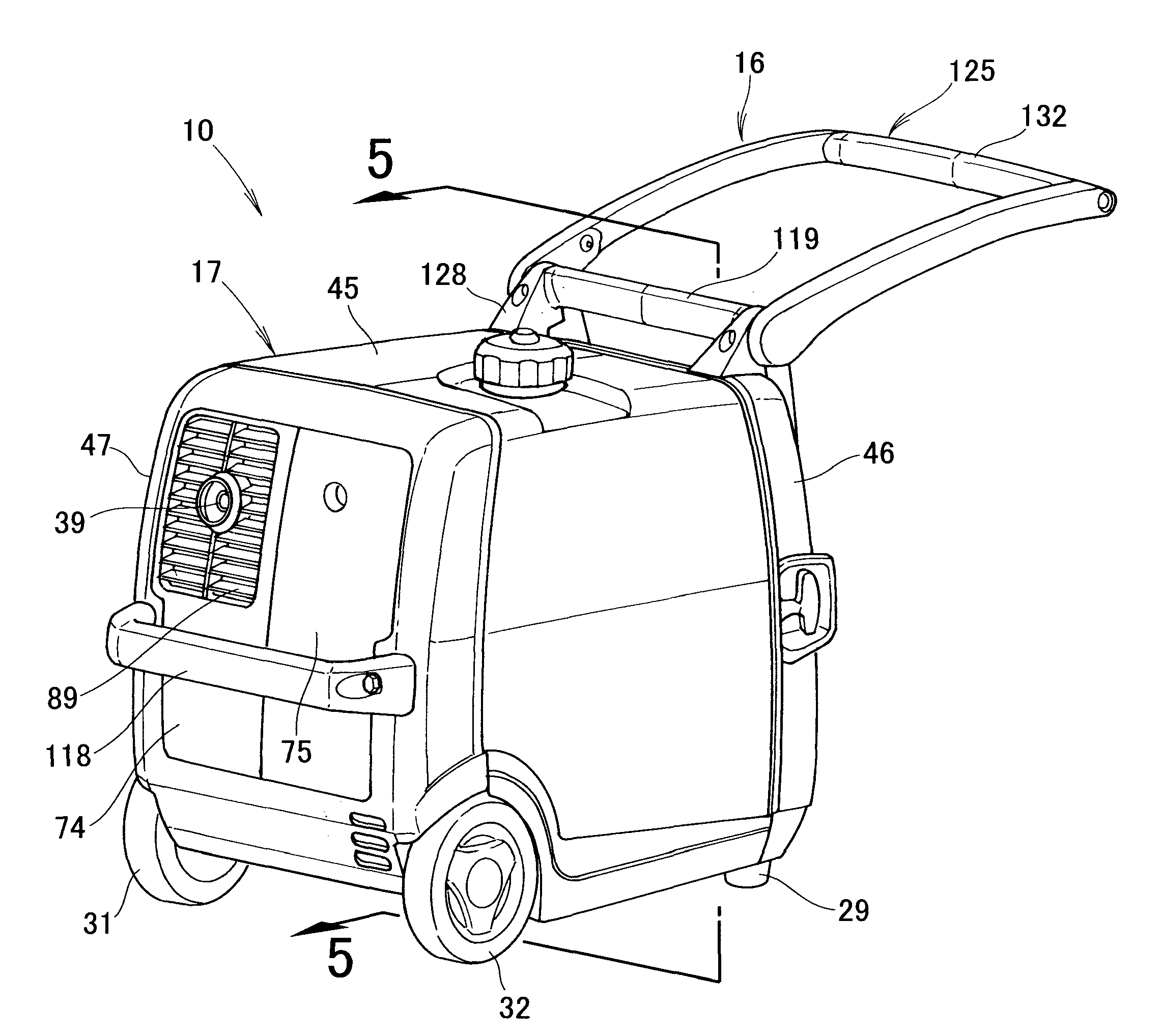
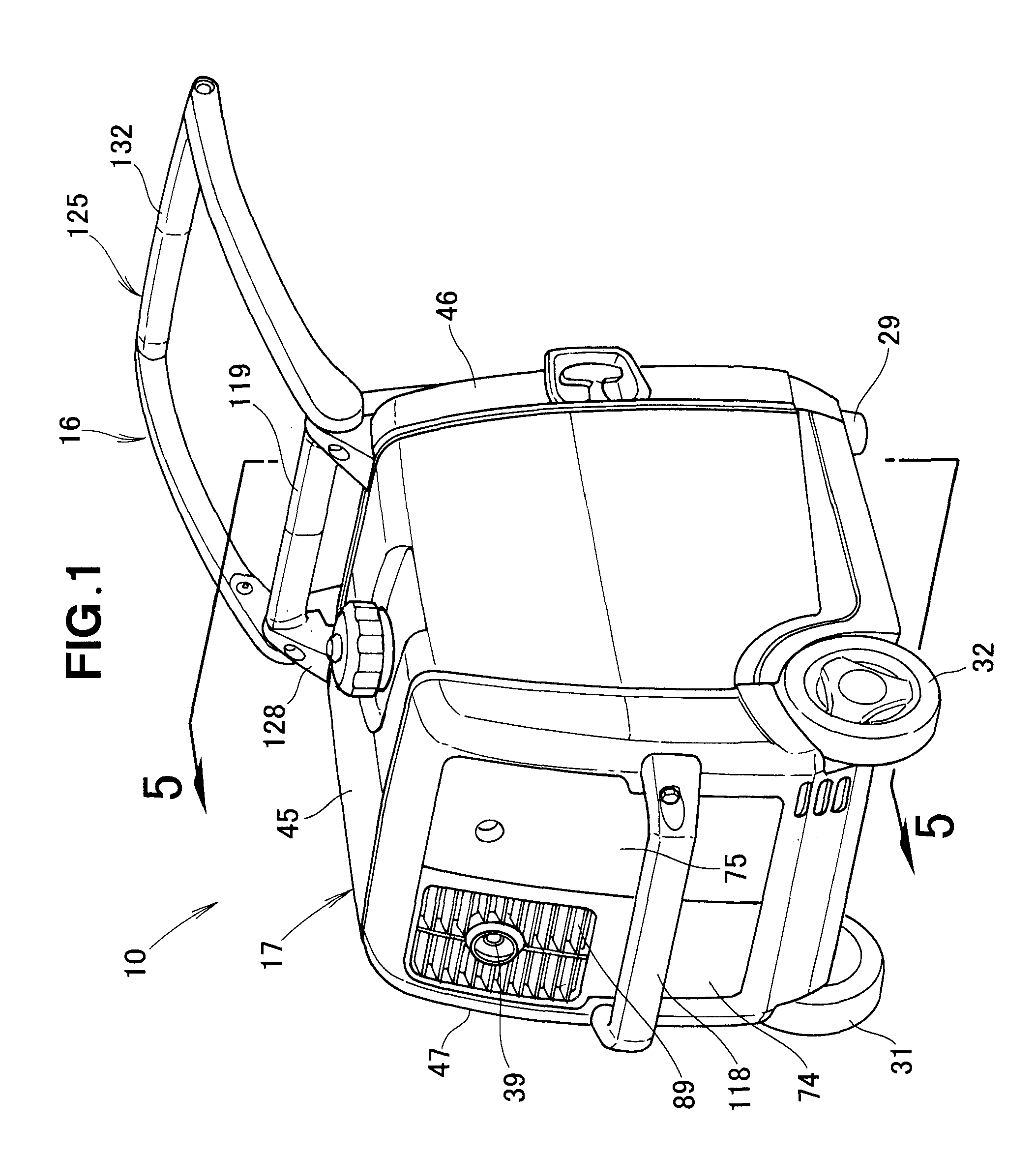
[0049]In the following description, the terms “forward” and “front” refer to a direction in which a human operator pulls an engine-driven power generator apparatus 10 of the present invention via a pulling handle 125.

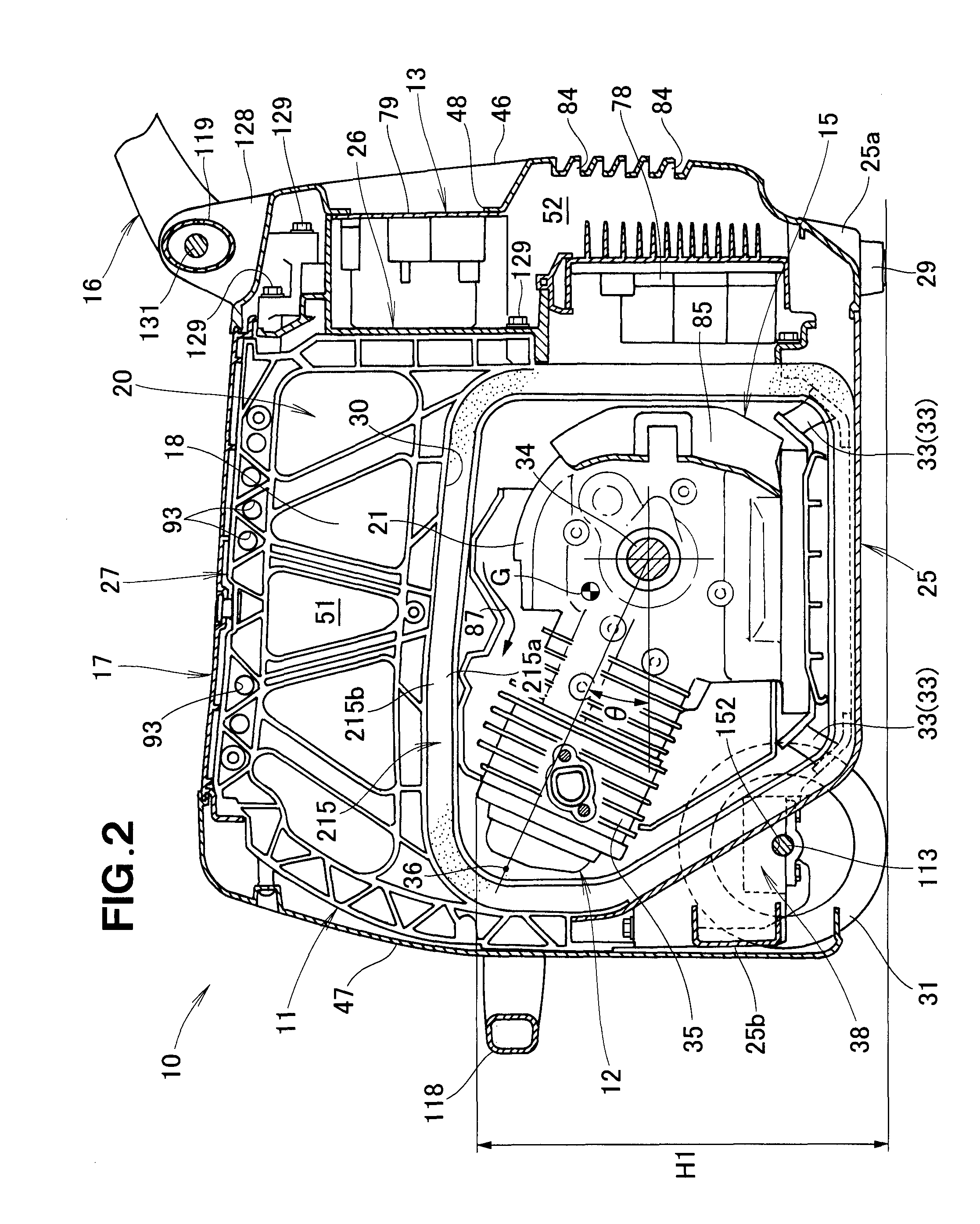
[0050]FIG. 1 is a perspective view showing an embodiment of the engine-driven power generator apparatus 10 of the present invention, and FIG. 2 is a sectional view of the engine-driven power generator apparatus of the present invention. The engine-driven power generator apparatus 10 includes: a framework unit 11 forming the body of the power generator apparatus 10; an engine / power generator unit 12 comprising an engine 21 and a power generator 22 drivable by the engine 21; an electric component section 13 for controlling the output of the engine / power generator unit 12; an air intake / fuel supply mechanism 14 (see FIG. 5) for supplying fuel to the engine / power generator unit 12; a cooling structure 15 for directing cooling air to the engine / power generator unit 12; a car...


PUM


Abstract

Engine cooling structure directs cooling air, introduced into a case by operation of a fan, to a cylinder block of an engine and then discharges the cooling air out of the case through an outlet port along meandering flow passages. Case cooling structure directs cooling along the inner surface of the case. Further cooling flow passage directs the air to vertically-oriented heat radiating fins so that the cooling air flows upward along the fins and then is discharged through the outlet port. Metal cooling-fan cover is supported by the lower cover via mounting members, and a resin-made cover guide is fastened to the engine together with supporting portions and interposed between the fan cover and the engine.

Description

FIELD OF THE INVENTION[0001]The present invention relates to engine-driven power generator apparatus where an engine-driven power generator is accommodated in a case together with the engine, and where the engine is fixedly supported by a lower cover via mounting members.BACKGROUND OF THE INVENTION[0002]Small-size engine-driven power generator apparatus have been known which include an engine for driving a power generator and a cooling fan connected to a drive shaft of the engine, and in which the engine and cooling fan are accommodated in a case and the case has an external air inlet port and a cooling air outlet port. One example of such small-size engine-driven power generator apparatus is disclosed in Japanese Patent Application Laid-Open Publication No. HEI-11-200861 (JP H11-200861 A).[0003]With the engine-driven power generator apparatus disclosed in JP H11-200861 A, operation of the cooling fan can introduce external air into the case through the external air inlet port so th...

Claims


Application Information

Patent Timeline
IPC IPC(8): F01P1/06F01P7/04
CPCF01P5/06F02B63/047F02B63/04F01P1/06
Inventor HIROSE, TADAFUMIYUKI, HITOSHIAOKI, TAKAYUKISHIBATA, RYOSUKEIIKURA, HIROKIUCHIMI, MAKOTOKAI, MASASHI
Owner HONDA MOTOR CO LTD
Why Eureka
Try Eureka